Custom 3D printer based on a repurposed autosampler robot
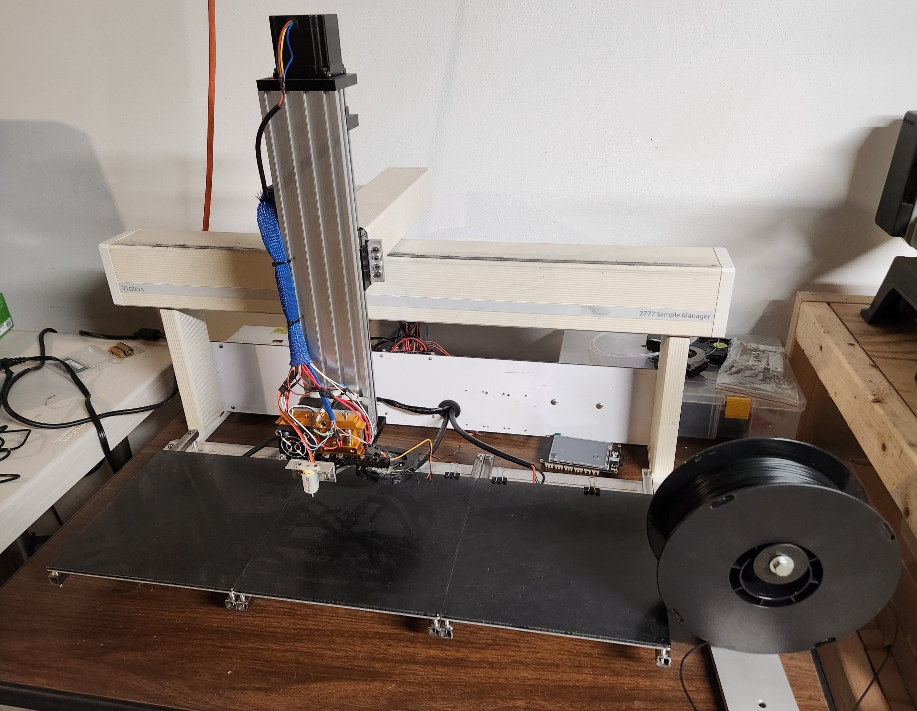
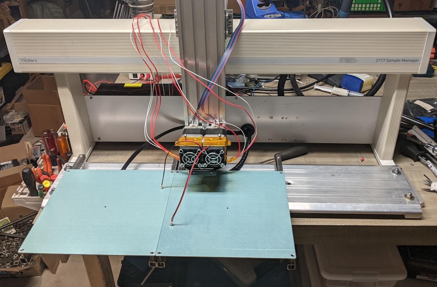
Having been gifted a Waters 2777 Sample Manager robot from a local biotech lab that was discarding old equipment, I decided to try my hand at turning it into a rather oddly shaped 3D printer. The original piece of equipment used a moving head to remove samples from tiny vials and inject specific amounts into fluid manifolds, and had cartesian coordinate system control, so it made a convenient platform to convert into a 3D printer.
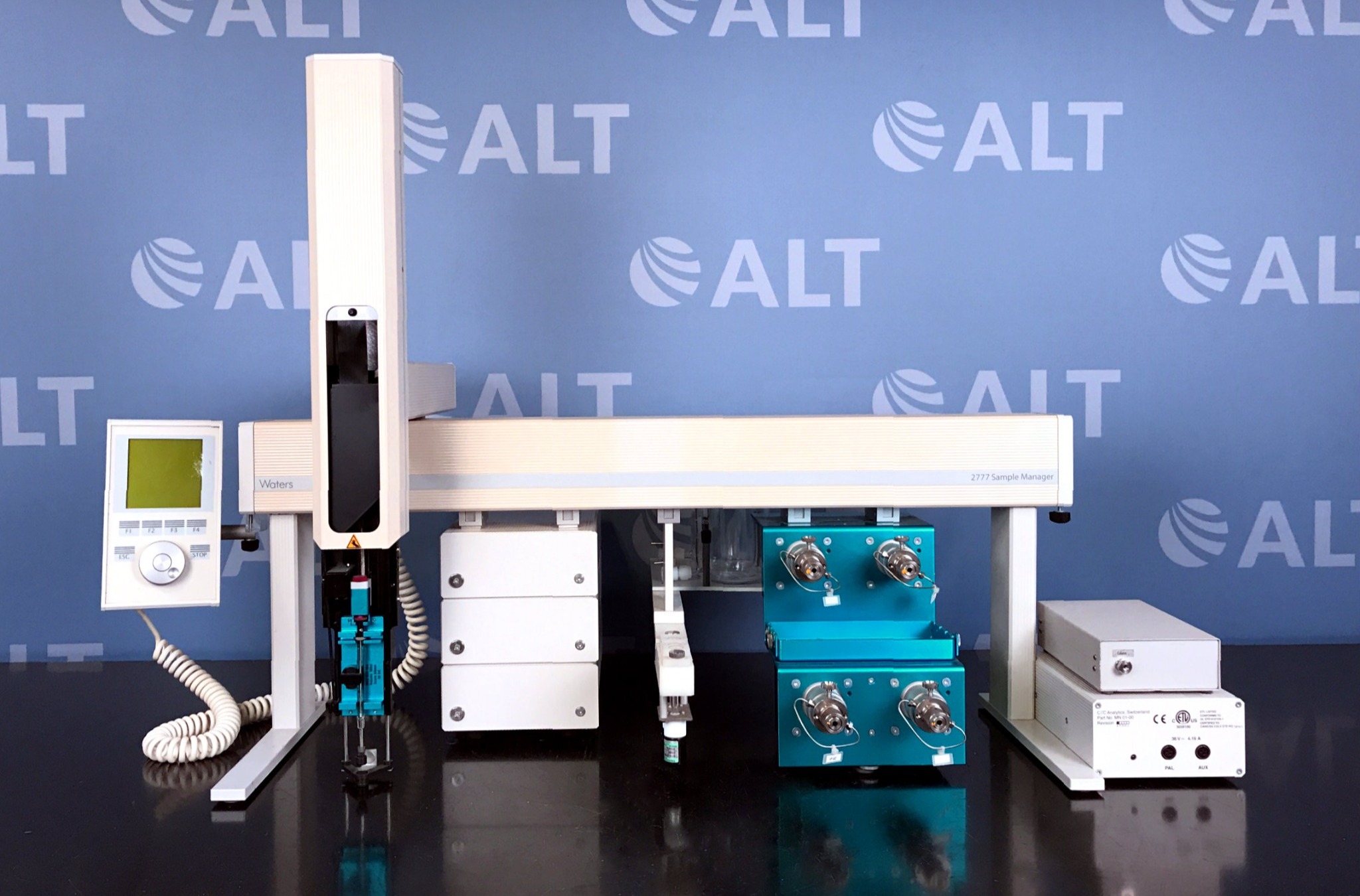
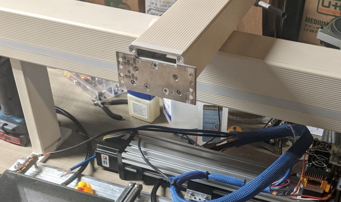
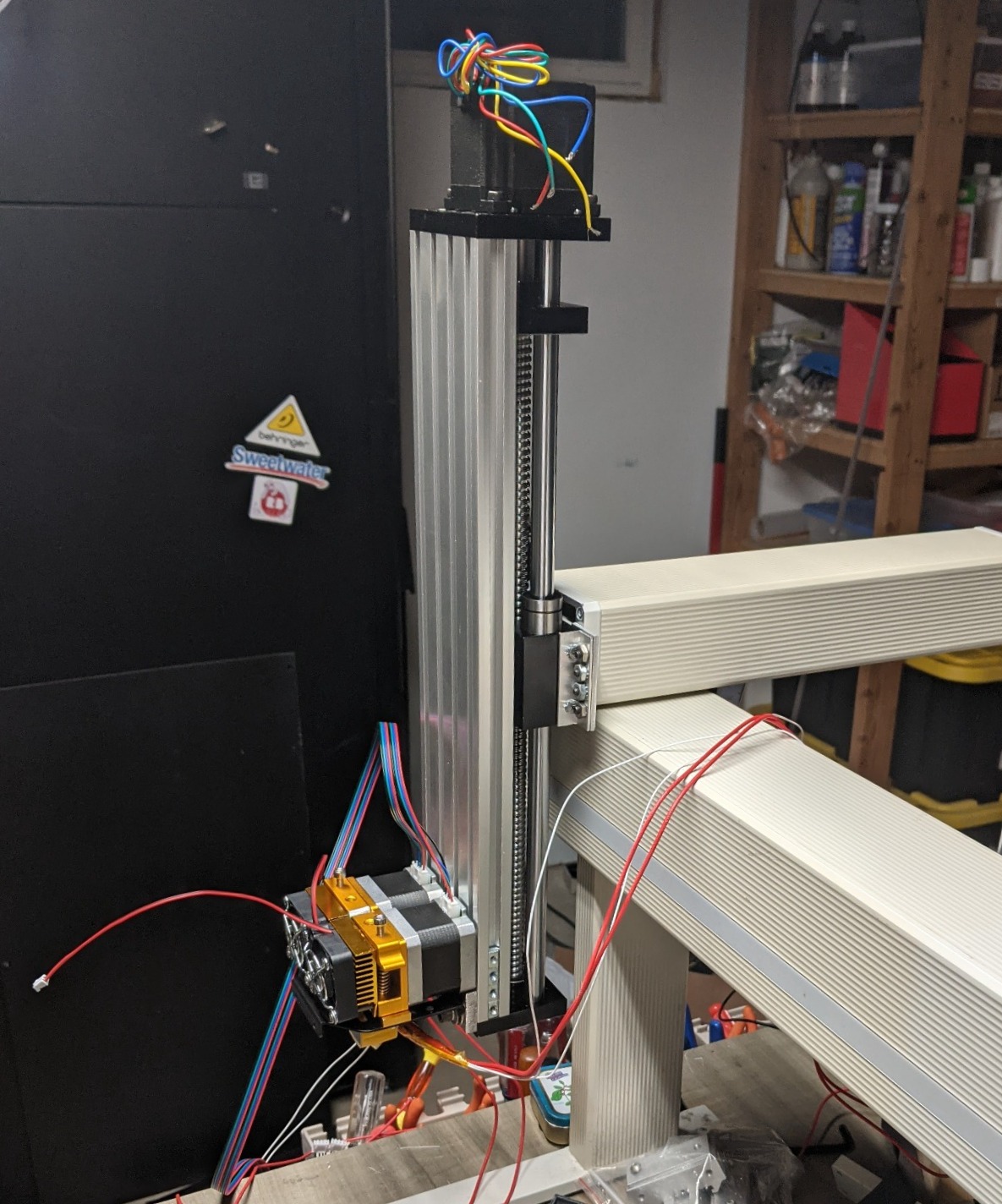
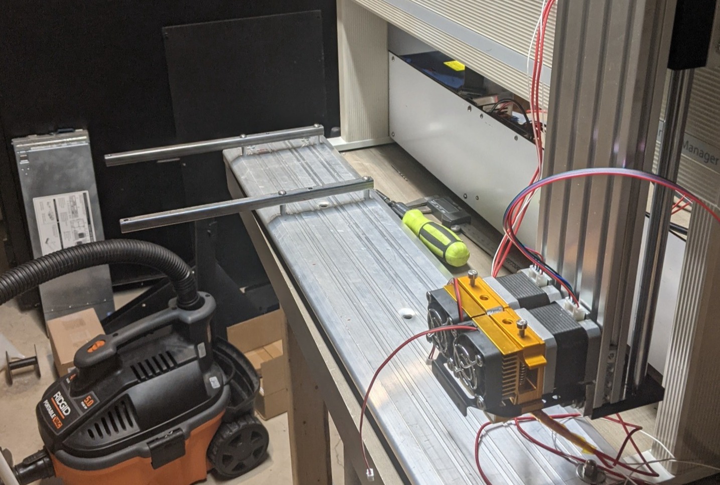
Unfortunately, as you can see in the photo above, the Z axis unit that was mounted to the robot significantly reduced its total height capability, and also relied on a stepper motor to hold the position of a rack and pinion system, meaning that any extra weight from the head would likely result in an overloaded motor. This also made pausing prints or generally powering off the machine potentially unsafe, as the head would immediately fall down. To solve this, I had to replace the head with something more sturdy that was also able to move precisely. Thankfully a product already existed to do this, a pre-made linear actuator with a ball screw and linear bearings for stabilization. After making an adapter plate to connect the new linear actuator to the front of the Y axis, I was finally able to mount it and work out how I wanted to mount the dual extruder I had purchased.
With the extruder mounted, I could then start to focus on building the bed area. Keeping the nozzle offset in mind, I planned to extend the beds out from the front of the unit on a fixed mounting plate, attaching them with a spring-loaded mounting system to be able to tension and adjust the bed leveling manually. I did this by running a section of stiff aluminum extrusion across the center of the printer and then rigidly attaching square steel beams that supported the beds.
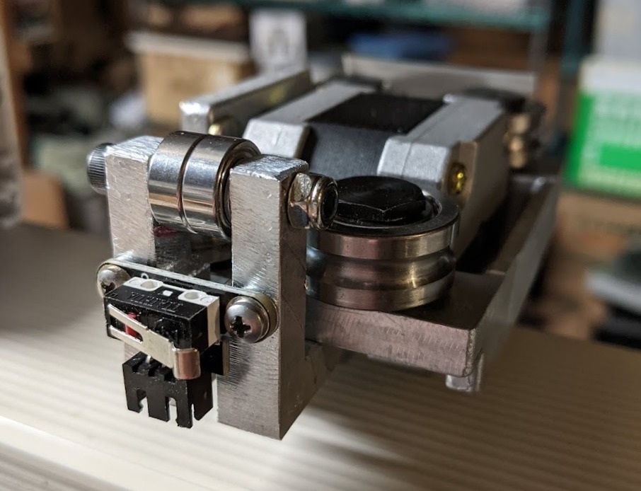
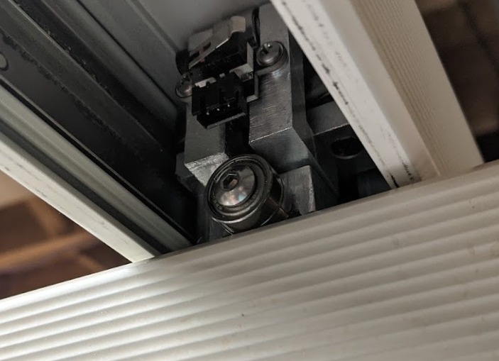
With all that done and the last beds installed, it was time to work on integrating all the systems together and wiring it for a first test. However, the hall effect limit sensors on the robot weren't compatible with my control board, so I had to solve this by installing mechanical limit switches inside the X and Y axes. This was quite simple for the X axis, as I could just stick one inside the end cap on the left side, which would bump into the carriage motor assembly at the limit. Unfortunately, the Y axis was a considerably more difficult challenge to solve. Due to the way the arm operated previously, it didn't bear much load, meaning that the Y axis would deflect downwards slightly while extending towards the front of the beds. This in turn was due to the X axis being stabilized using a set of 4 U-groove bearings that weren't able to handle the strong perpendicular load they were put under at full extension. To remedy this, I had to add an additional set of bearings to brace the Y axis's travel to compensate for the lack of rigidity in the X axis, as well as another set above to prevent the Y axis U-bearings from deflecting. This also happened to provide a convenient mount for the Y axis limit switch.
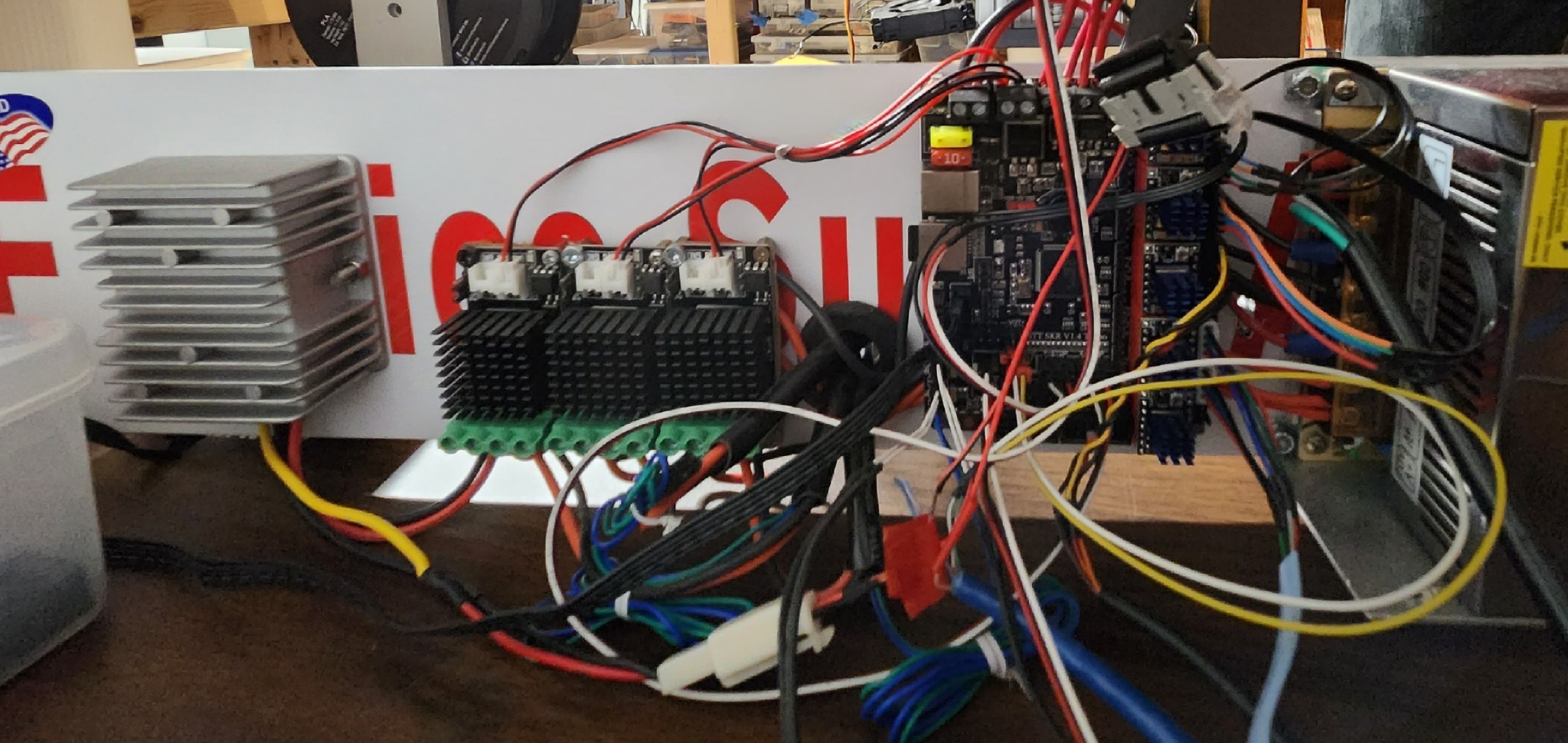
At this point, I had also constructed the back panel of the printer which mounted to the legs at the sides and held all of the control electronics and power supplies. I was working on this in tandem with attaching the beds. From left to right there is a 24-12v regulator for the fans and some other low voltage hardware, three MOSFETs boards for the heated beds (the control board has one, but it can't handle the current that all three beds draw together), the control board (a bigtreetech skr v1.4 turbo) and then finally the 24v DC power supply.
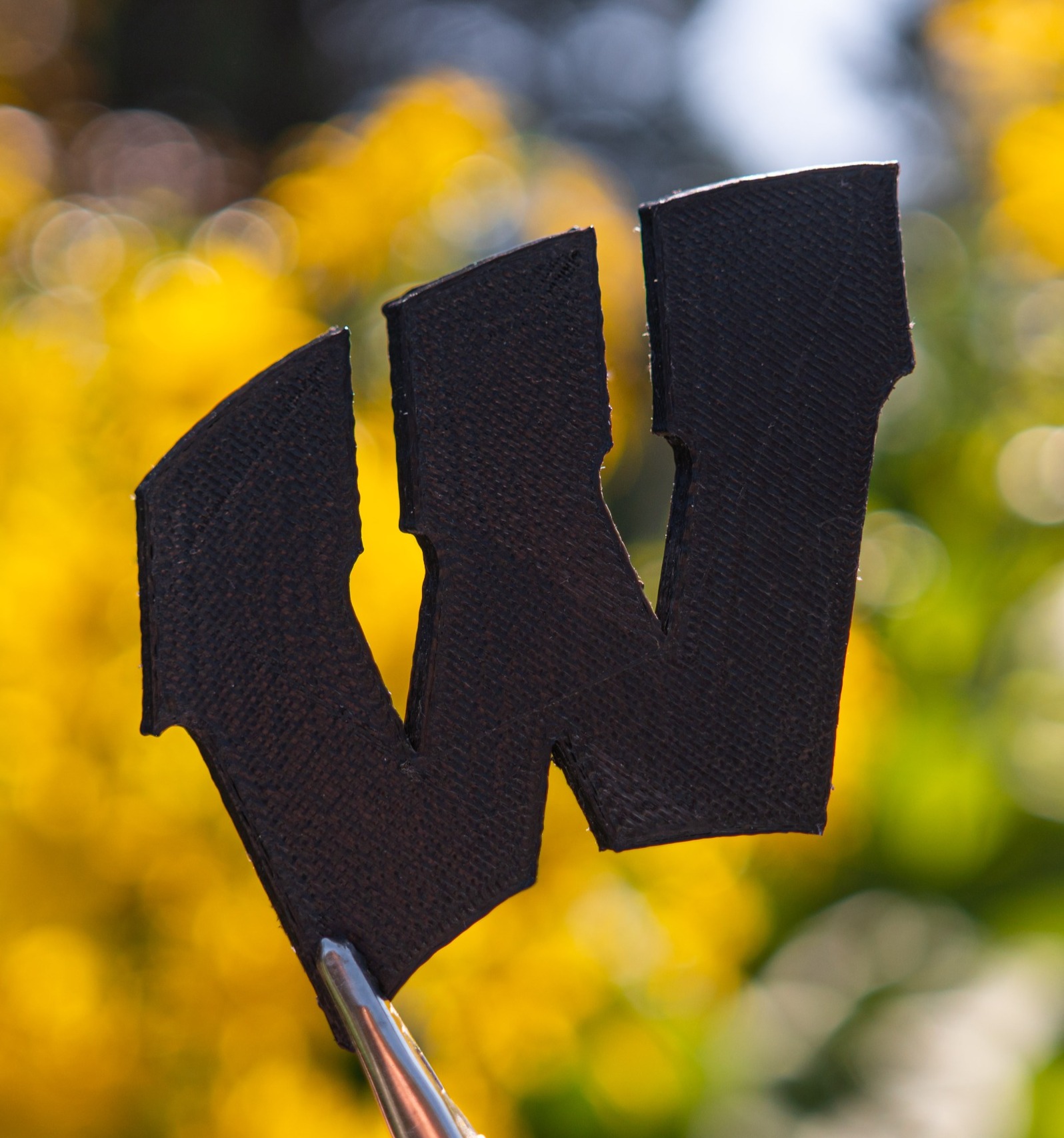
After all this, I was finally able to calibrate and run first test prints on the printer, which worked amazingly well for the first time printing!
For my UW-Madison application, I printed out a school logo with black PLA:
Post a comment