BSR Solar Car 1.5 Battery Design Process
As the current Mechatronics lead of Badger Solar Racing, my main responsibility this year has been to redesign our main battery pack for our first solar car, Solar Car 1. As part of a large set of upgrades being made to our car, our battery pack had the potential to improve a considerable amount, as the old battery pack suffered from several non-fatal issues. The most prominent issue was the ease of removal. During the competition, at least twice a day (once in the morning and once at night) the pack must be installed in and removed from the car. The previous system consisted of two straps that ran around the perimeter of the pack in a groove to provide balanced support on the enclosure. These straps were then hooked to an engine lift crane, and the battery would be slowly lifted out, moved to the side, and set down onto a cart.

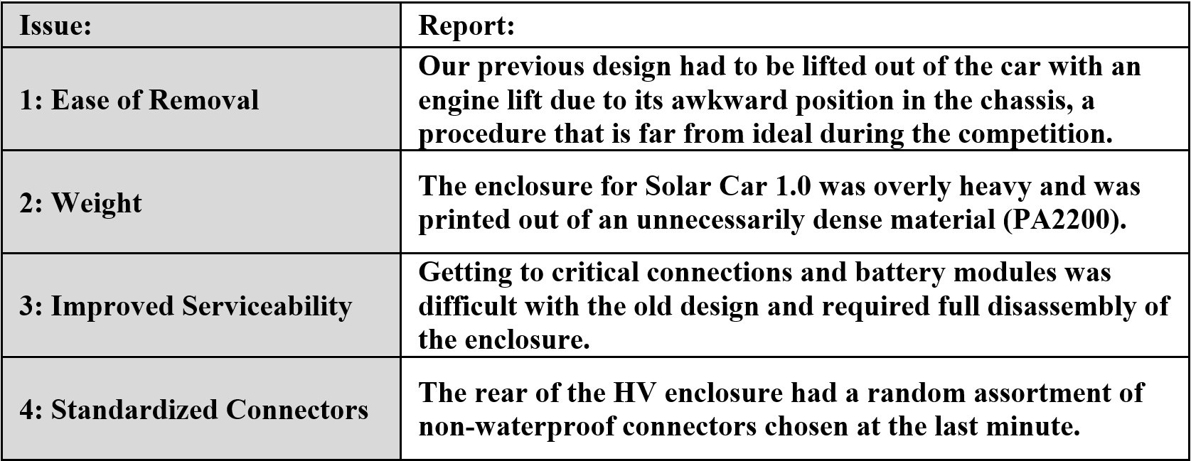
The original design for Solar Car 1's battery pack was made in a very short time due to the design work getting passed on to me from the previous mechatronics team lead right before last summer's competition, and it had four major flaws summarized in the table below:
Topic 1: Ease of Removal
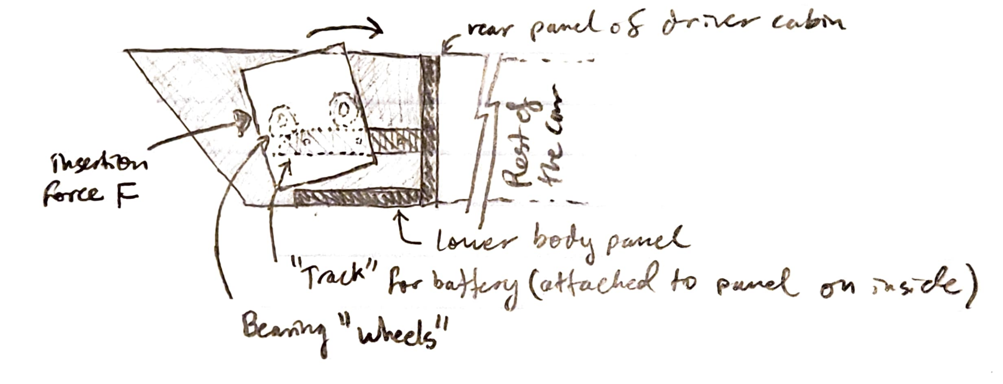
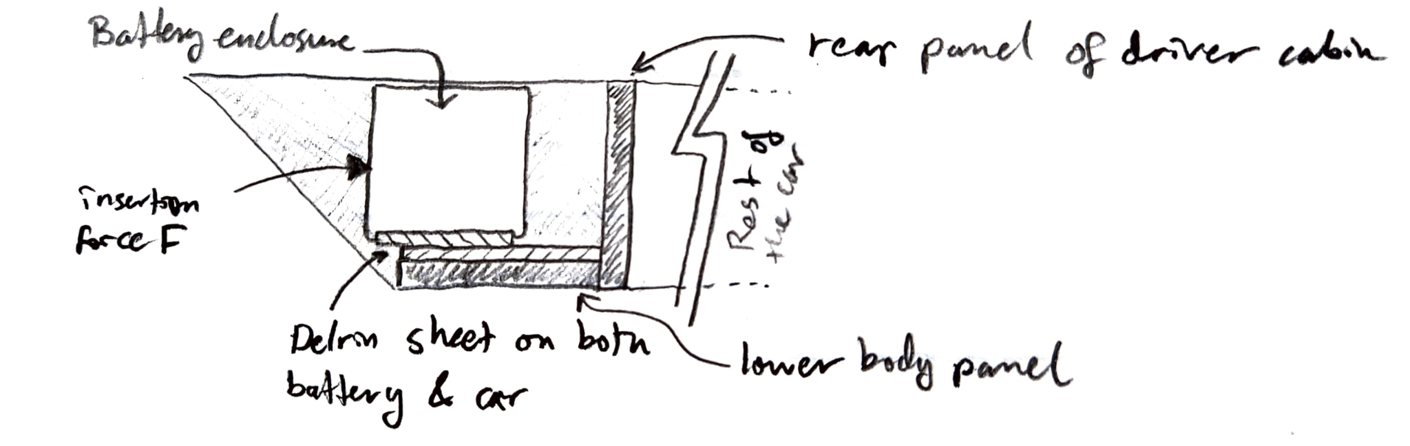
The first was the incredibly inconvenient method used to insert and remove the pack from the car. Removing the battery enclosure from Solar Car 1 was not an easy task. To fix this, the free space at the rear of the car’s chassis behind where the battery sits was considered as an alternate removal path. Rather than removing the pack vertically, it is possible to remove it horizontally by translating it out the back of the vehicle onto a suitable platform or ramp.
A potential pitfall of this method however is the high frictional force to pull the battery pack out of the spot where it sits during operation. Two solutions for Solar Car 1.5 were developed to mitigate this:
Method 1:
The first design concept is a simple sloped profile, with one profile mounted on each side that acts as a rail on which large bearings fitted to the outside of the battery enclosure roll. This method would keep the battery enclosure from touching the bottom of the car, distributing all load through the large side-mounted bearings.
Method 2:
Low friction polymers such as Delrin or UHMWPE are commonly used to reduce friction in assemblies or parts where metal bearings are not ideal, or where surface friction between two parts needs to be low. The second design for the battery removal system focuses on the latter of those two uses, and a plate of Delrin is specified to be installed both on the bottom of the battery enclosure as well as on the top of the “lower body panel” as seen in Figure 4.
Assessment of Methods 1 and 2:
Due to the extra complexity of parts, tight tolerances for alignment, and high shear stress on small sections of the outside of the battery enclosure that would be present with the rail system, the low friction polymer system was chosen for its simplicity and ease of implementation. To ensure that at a worst-case scenario the enclosure wouldn’t be too hard to move, a simple static analysis was done based on friction coefficients from the Delrin design guide, assuming a battery weight of approximately 110lb.
Analysis and Design conclusion:
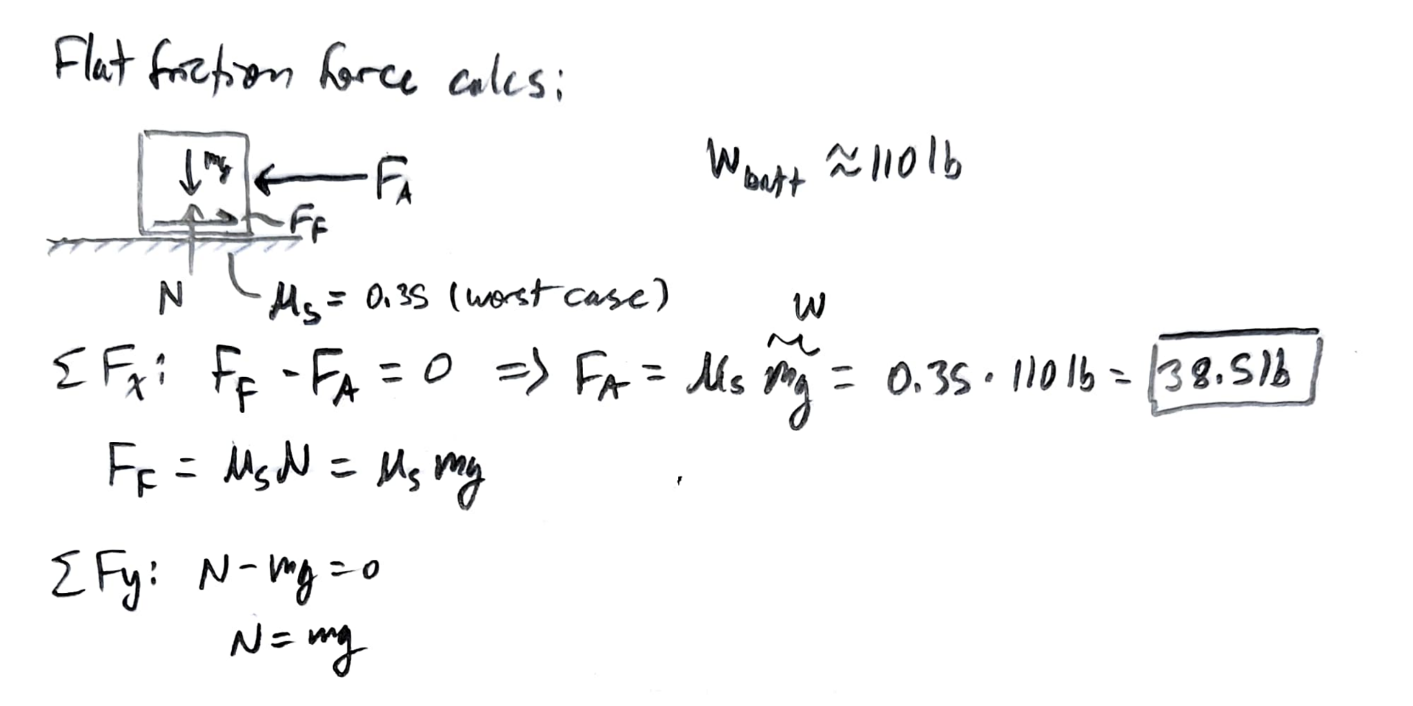
Results from this analysis show a very promising force for removal of 38.5lb, a value that most people should be able to provide with their own strength, even with the worst-case friction coefficient. In theory, this method of removal proves to be a very simple and effective system compared to the rails, securing its place as the final choice for the enclosure removal redesign. Unfortunately the team will still have to develop a custom scissor lift or ramp to remove the enclosure using either method due to ground clearance issues, however with the low friction polymer solution, no extra work needs to be done to allow it to keep sliding onto another platform. Simply adding a Delrin sheet to such a tool would solve the same issue on the removal side. Although this method still requires a tool, it should be considerably smaller and lighter than the engine lift used for Solar Car 1. For future designs in Solar Car 2.0, the team is planning to switch to a more energy-dense battery chemistry which should make the pack possible to lift by hand.
Topic 2: Weight
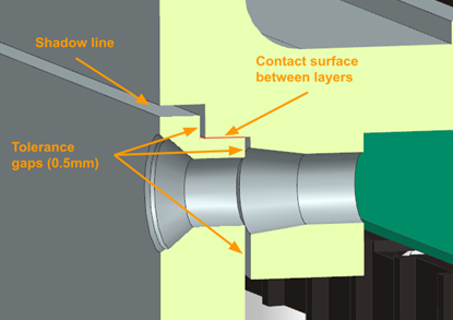
An exceptionally simple method for weight reduction that had not been explored was switching to an alternate 3D printing material. Solar Car 1 used Nylon 12 (PA2200) with a density of 930 kg/m³ and ultimate tensile strength of 50 MPa according to manufacturer specifications. An alternate material with the added benefit of fire resistance is Nylon 11 (FR-106) with a greatly decreased density of 450 kg/m³ and comparable ultimate tensile strength of 46 MPa according to manufacturer specifications. Our industrial 3D printing sponsor, Prototek (formerly Midwest Prototyping), supplies this material as an option for their SLS production capabilities. This material change alone greatly reduces enclosure weight, however there was room for optimization within the 3D models. To achieve this I created a simplified modular layer design with thinner wall features. Compared to the monolithic enclosure design used in Solar Car 1, this design combines layer separators and the monolithic external enclosure structure into a set of modular layers. Taking inspiration from injection molded enclosures and applying those techniques to industrial additive manufacturing, I designed a module layer system that uses shadow lines. This helps to bear weight between module layers and provide structural rigidity for the top of the previous layer.
The battery enclosure is not only responsible for housing the battery cells on the solar car, but also all the high voltage electronics required for the car. The uppermost module houses all this hardware and was the heaviest part of the battery enclosure on Solar Car 1. The new design for the high voltage enclosure on Solar Car 1.5 is very similar to the battery module layers, aside from being several millimeters taller to accommodate the Orion BMS system the car uses for battery protection. Shortening this compared to the high voltage enclosure on Solar Car 1, plus the decreased per-layer height led to a 2-inch decrease in overall height, aiding in the enclosure’s removal from the back of the car.
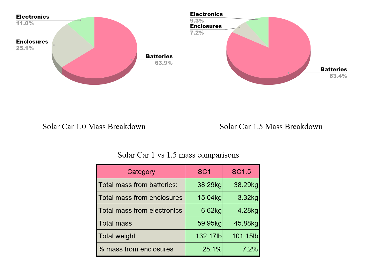
To visualize the vast difference in weight between the new version of the enclosure and the old version, I weighed all of the components within the enclosures, and created mass estimates based on volumetric data from Siemens NX and density of the 3D print materials.
Topic 3: Improved Serviceability
The serviceability of the battery was unfortunately subpar on Solar Car 1, as I didn't have much time to think about it while making the design. To access critical components, the entire high voltage assembly had to be removed in addition to all the harnessing. In the new revision of the enclosure, small access panels which double as intake vents have been added to the rear to make accessing the harnessing and bus bars easy.
As seen in Figure 9, there is a DB67 connector to allow for disconnecting all low voltage connections on the current layer. Depending on the layer, this will handle connections for the fans, thermistors (80 total), and voltage taps for the BMS. Additionally, all layers are held together by only 6 countersunk screws, so disassembling the layers if needed should not be difficult.
Another consideration I took into account is safety during service and operation. To evaluate this, the conductivity of the PA12 and PA11 materials used to 3D print these enclosures must be considered. Both prove to be a completely safe option with respective minimum resistances of 100MΩ and 1MΩ respectively. According to the Megger Guide for Electrical Insulation Testing, 1MΩ/1000V is the minimum standard for electrical insulation. With a maximum working voltage of 150V on Solar Car 1.5 systems, neither material comes close to exceeding this minimum limit. Additionally, the PA11 material Midwest Prototyping provides has fire resistance capable of passing the FAR 25.853 60s vertical burn test.
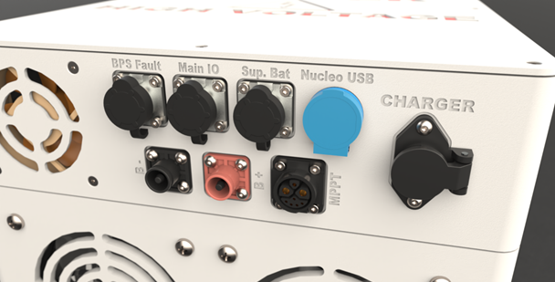
Topic 4: Standardized Connectors
Solar Car 1 had a random assortment of connectors collected from the team workspace, mostly consisting of D-Sub connectors. These connectors, although cheap and readily available, are not meant for automotive applications, and therefore are not water or shock proof. They are also very limited in standard configurations, meaning multiple connections with very different electrical purposes had identical connectors. To solve this for Solar Car 1.5, IP67 rated connectors with different pin counts and styles were ordered to prevent mis-plugging them, with a consistent type of connector used depending on the type of connection. A waterproof connector for external USB access to the internal microcontroller was also added.
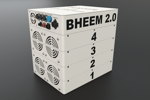
Results and Concept Renders
The new design for the Solar Car 1.5 battery enclosure that I created was completed on the intended schedule set by myself with the mechanical team and implements all the features and improvements summarized above. Manufacturing with Midwest Prototyping will begin over the end of fall 2023 winter break. Small design validation prototyping using FDM 3D printing has taken place throughout the semester to check fit and dimensions for critical components such as connectors or heat set inserts. Figure 11 shows a final render of what the Solar Car 1.5 battery enclosure will look like after printing and assembly
Real world results
Finally after much waiting, the parts were manufactured by our sponsor and ready to pick up. Fit on basically everything was perfect first try, which was an incredible feeling!
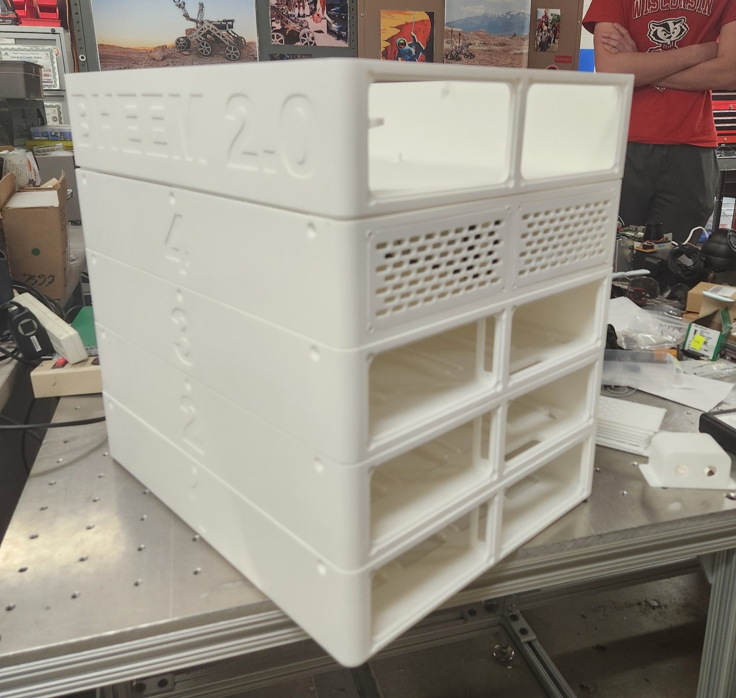
The pack is assembled in layers, starting from layer 1 and working upwards:

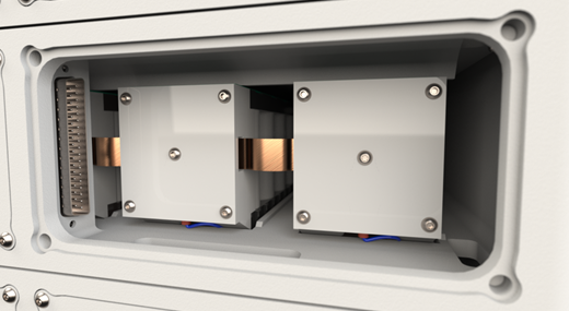
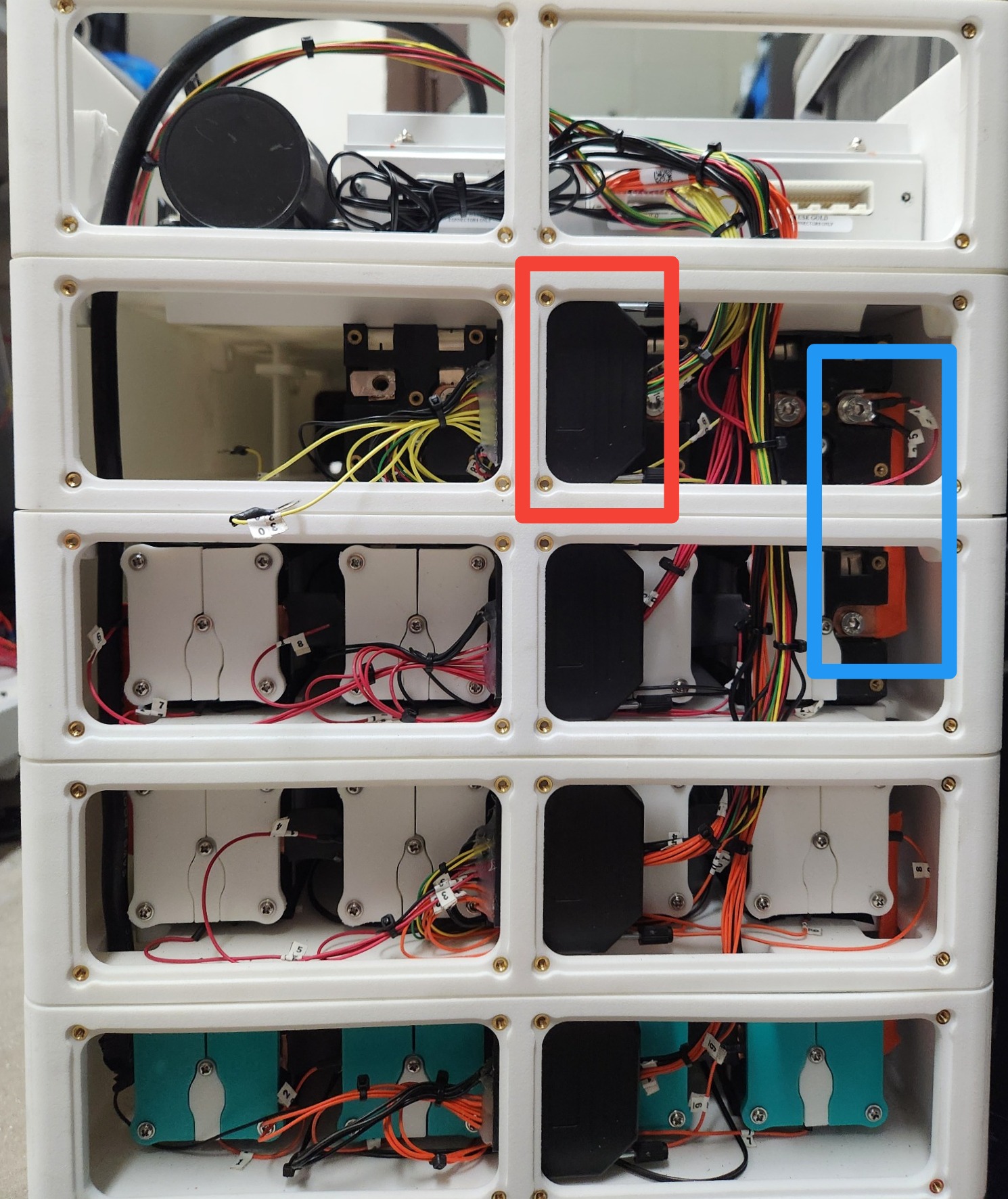
High current connections between layers are achieved with metal busbars highlighted below in blue that span between every level. A large 6AWG wire runs from the main negative side of the pack at the very bottom up through all layers. During disassembly, this wire must be fed back out of the battery pack before the layers can be separated. All battery voltage taps, fans, and thermistors are run through the D-sub connectors highlighted in red below, allowing for much easier disassembly.
Post a comment