Hand building a 600 cell lithium ion pack for a small EV
This is the process I went through to build a large scale, modular battery system with internal heaters for a 3 wheel electric motorcycle project I am working on. Since the battery was a large enough undertaking on its own, I feel it deserves its own project page.
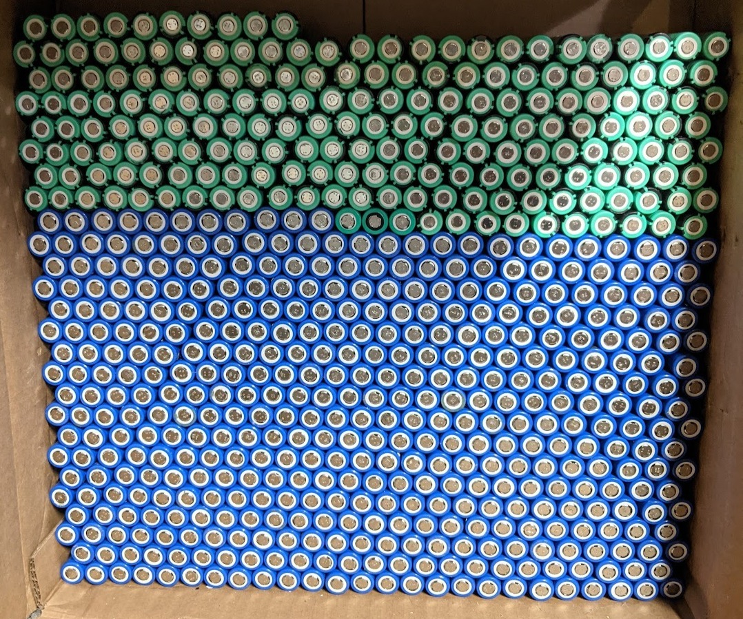
Building the battery modules started off with 18650 cell recovery from wireless security camera batteries that I ordered off battery hookup which is an excellent source of overstock cells.
I recovered two very similar models of cells from these packs, NCR18650A cells from Panasonic, and LGABD21865 cells from LG with 3.1Ah and 3.05Ah capacities respectively. All cells were charge/discharge/charge tested in Liitokala Lii-500 and Opus BT-C3100 cell testers, and the values of capacity were recorded on the outside of the cells by marker. All cells were left for at least a month to verify voltage would not drop outside of tolerance within that period, any cells that did were discarded (very few suffered from this). Overall, I was able to recover 623 good cells from the packs (out of ~ 628 total).
The scrapping process
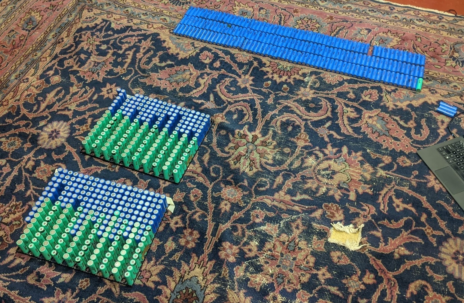
The next step was to lay out the pack design and group the cells by capacity so the pack was as balanced as it could be when it was built. I chose to build the modules with 10s 30p configuration for a total of 300 cells per module. With nominal capacity in the cells, the two modules in this pack hold a total of 6.9KWh of energy, which should provide ample range for the vehicle I'm building. Using https://www.repackr.com/, I paired all 600 cells to create packs with minimal capacity deviation, and began to assemble the cells into their final layouts in the standardized 18650 holders I purchased.
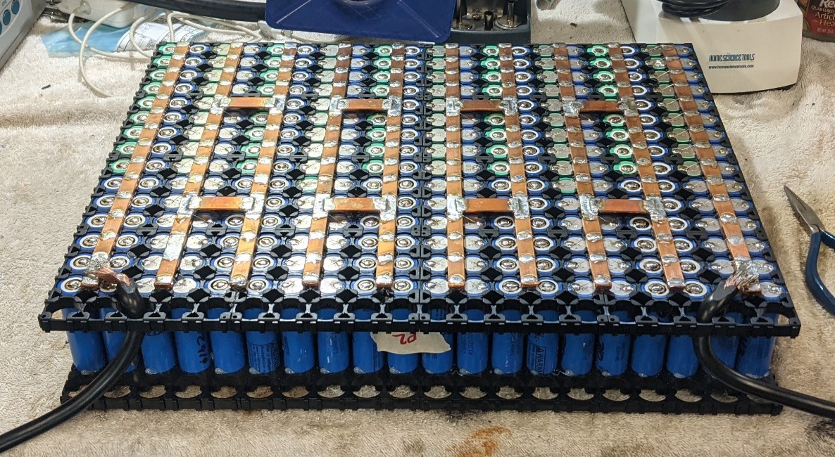
Once the packs were laid out and the cells were prevented from rotating using silicone caulk, I was ready to begin wiring them together. I chose to go with a per-cell fusing system on these packs, since I wanted to ensure safety if one cell in a parallel set were to fail closed. I achieved this through a busbar/soldering system which is practically the only way to do this at a small scale (the alternatives being extremely small scale spot welding, laser welding, or ultrasonic welding). The technique I have developed through extensive testing and prior battery pack design introduces the least amount of stray heat into the battery cells to reduce potential damage from heat. This involves using a tool to first rough the surface of the cell to ensure good solder adhesion. On the negative side, this is done towards one side of the cell housing to make sure that extra heat is distributed into the cell wall rather than the battery substrate. Then liquid acid-free solder flux is deposited onto the roughed surface, and finally a high temperature soldering iron with a flat-ended tip is briefly used (<0.5s) to "tin" the top of the cell. By doing this, the cell never experiences extreme heat for more than a brief moment, and the temperature quickly falls.
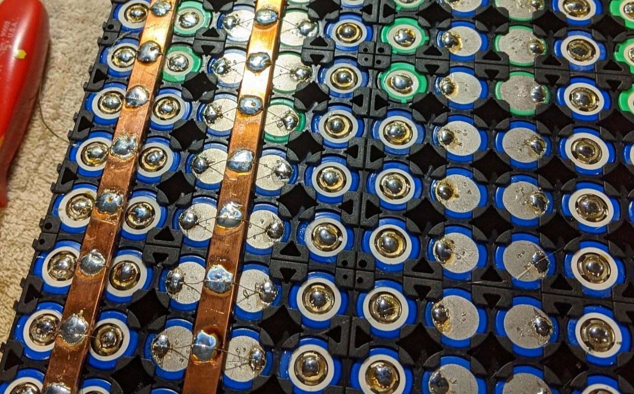
Cell-level fusing is visible on the left of the above figure. A single tinned copper wire is strung between each end of the batteries in a parallel group and over the copper busbar in the middle. This creates a weak spot in the middle of the wire where it would burn if it experiences high current (such as a single cell failing as a dead short).
On the right, the cell "tinning" method mentioned previously is visible. This makes it incredibly easy to attach the wires, since it requires very little heat to remelt the solder and add the fusing wires.
In the next figure, series busbars can be seen attaching each parallel set to the next to create the 10s30p configuration for each pack. These were added using a 250W pipe soldering iron, since the large copper busbars were incredibly difficult to solder to. The soldering was also thermally insulated from the cells by the black plastic holders which are made from ABS-PC, a heat resistant material commonly used for battery cell holders. In a very similar fashion, I also added the large main positive and negative 4AWG wires that attached to the busbars (unfortunately I only had one color).
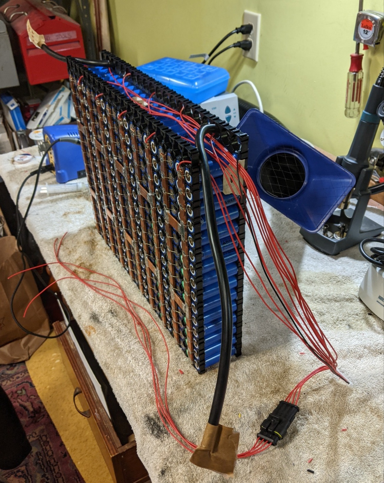
The final steps involved adding the connections for the battery management system (BMS), the heating pads, silicone insulating pads, and finally epoxy-fiberglass laminate sheets to protect and insulate the batteries.
I started with the BMS wire taps which had to be soldered to each parallel set:
Next, I moved on to the heating pads and insulation. Unfortunately the documenting side of me forgot to take photos of this part (I was incredibly excited to finish the packs) so there are unfortunately no photos of that). However it basically consisted of using thin silicone craft mats and suitably sized 30°C RV tank heaters that I purchased off of Amazon. These were semi-permanently attached to the outside of the battery packs using vinyl electrical tape.
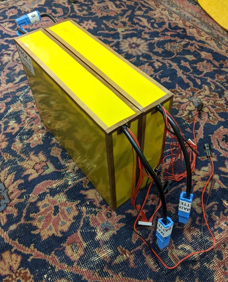
Finally, the hardest part of protecting them was cutting all the right sizes of epoxy-fiberglass laminate. I did this by measuring the largest final outer dimensions of the battery modules, using fiberglass tape to bridge the corners of the boxes. I was able to cut the composite sheet just using a pair of scissors along the grain which made the process far safer. This resulted in the final boxes which can be seen below:
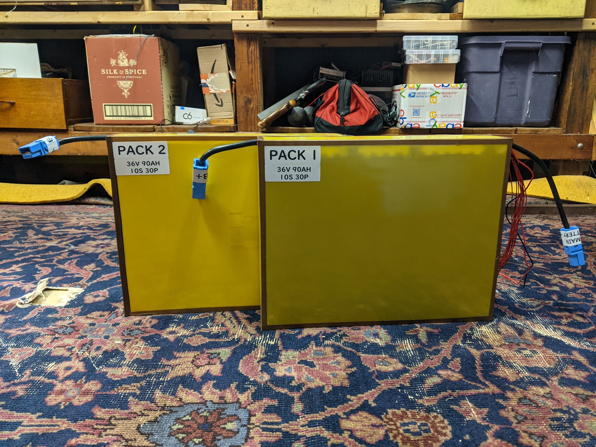
These have since been installed on my 3 wheeled electric motorcycle! From some preliminary testing on there, they appear to be performing excellently! I am incredibly happy with how they turned out.
Post a comment