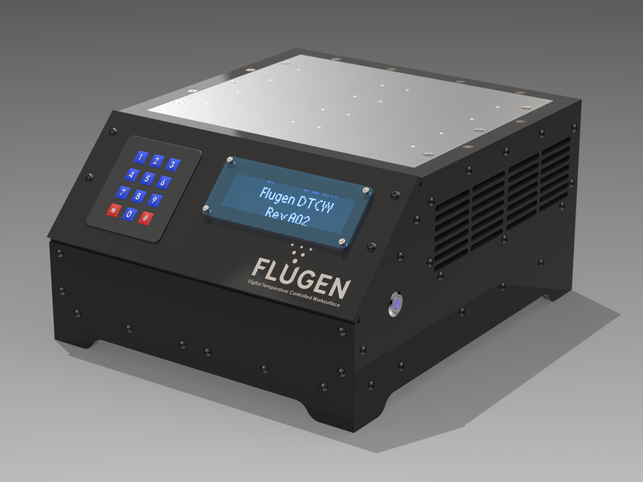
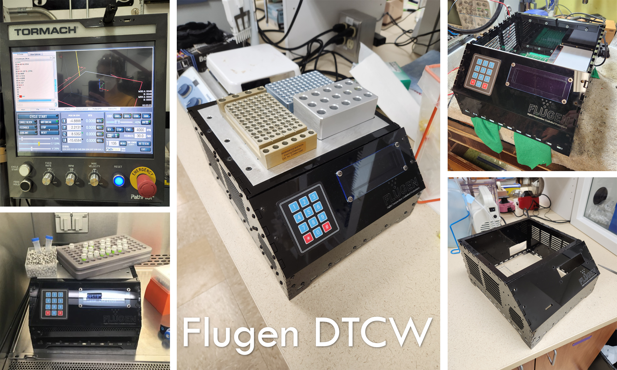
Digital Temperature Controlled Worksurface
A block diagram showing a basic layout of the systems inside it is depicted below.
The Digital Temperature Controlled Worksurface is a temperature-controlled metal work surface for lab assays capable of cooling to 4°C minimum and heating to 60°C max for use in a variety of lab assays. It was a concept-to-product design I completed for FluGen, Inc., a flu vaccine R&D company in Madison Wisconsin.
Architecture:
The Digital Temperature Controlled Worksurface or DTCW for short uses four TEC 12712 thermoelectric cooling modules to achieve cooling and heating power on the upper aluminum plate. These are connected to large copper heatsinks with fans which dump heat from the plate plus excess heat generated by the TEC modules during operation.
A closed loop PID controller operates the modules through a H-bridge which can change the current and polarity of the 12v 1100W supply to maintain a constant temperature across the aluminum plate during operation.
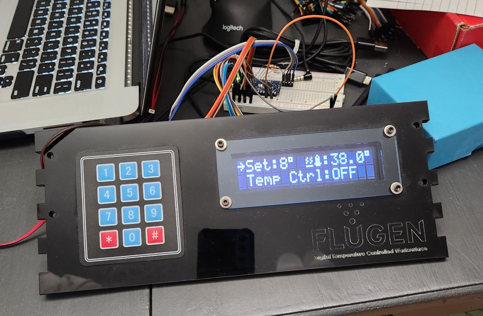
Finally, a user-controllable front panel provides an intuitive menu system which can be used to enter a temperature setpoint, change settings such as PID tuning and sensor calibration offsets, and run diagnostics on the device.
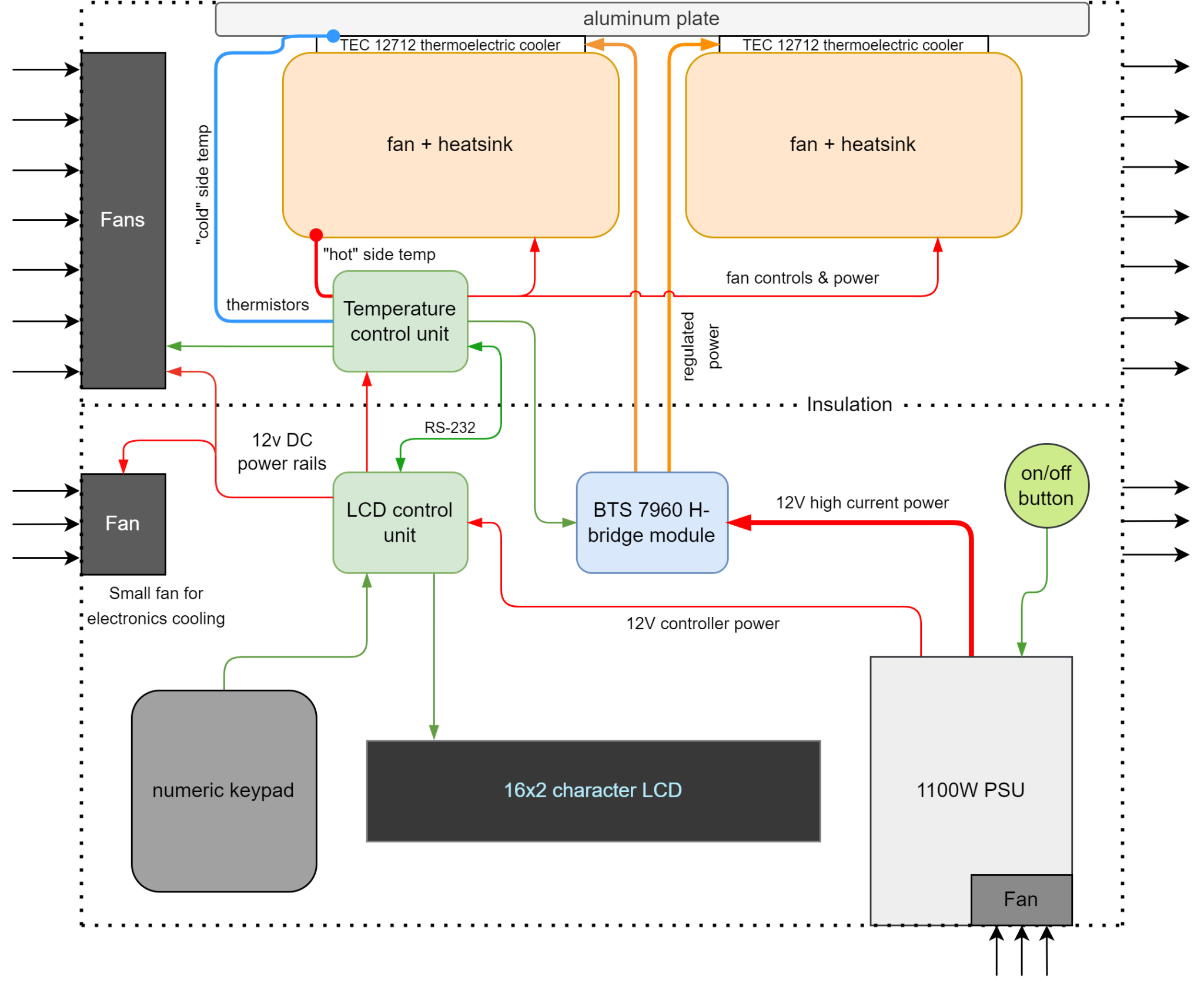
The system operates using two separate microcontrollers. One handles all user input and draws the menu system on the LCD (referred to internally as the LCD microcontroller), and another handles the state machine and PID control loop that operates the cold plate (referred to internally as the TCU, or Temperature Control Unit). The second microcontroller is also responsible for reading the NTC Thermistor temperature probes and controlling the cooling fans' speeds.
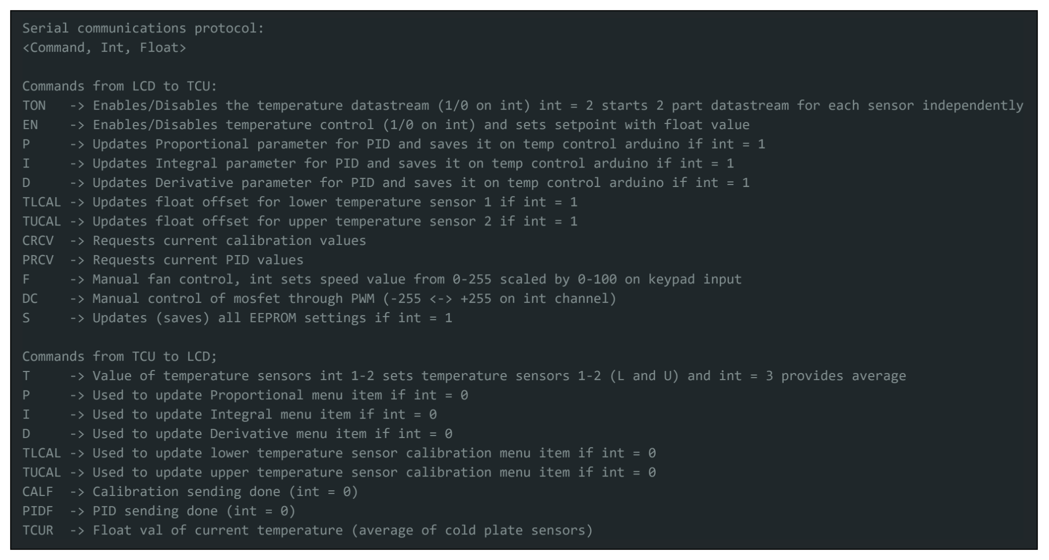
To allow consistent communication between both microcontrollers, I developed a simple serial protocol with commands that could be sent between both Arduino microcontrollers using the Arduino softwareserial library so that the host Arduino's USB serial port could still be used.
The final summary of all commands that the systems (LCD and TCU) accepts is shown below:
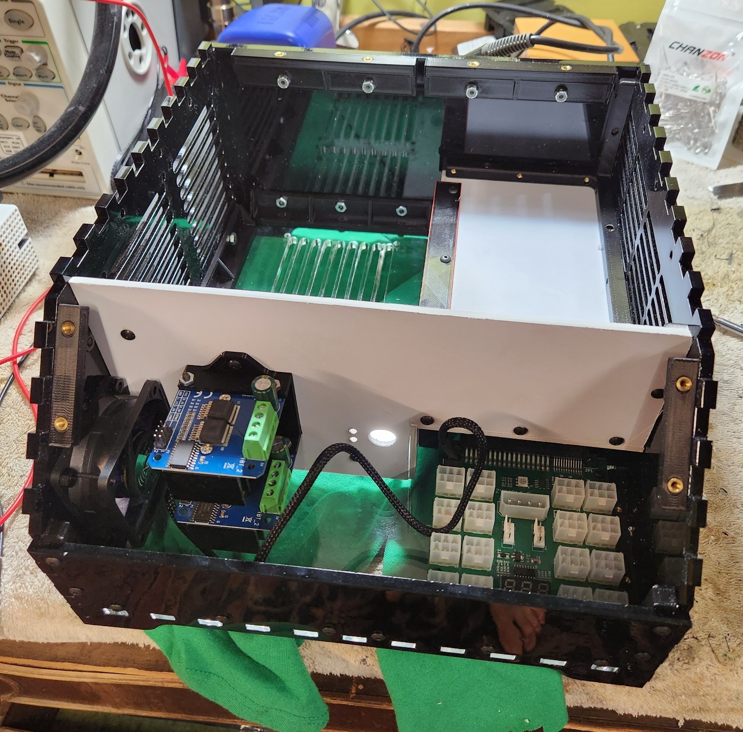
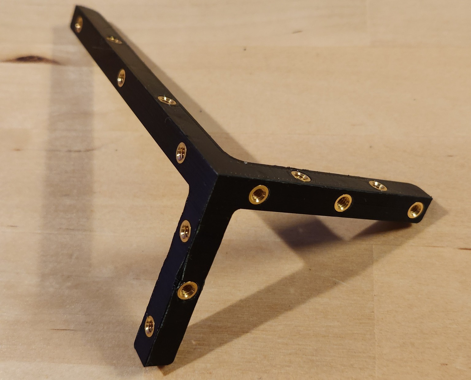
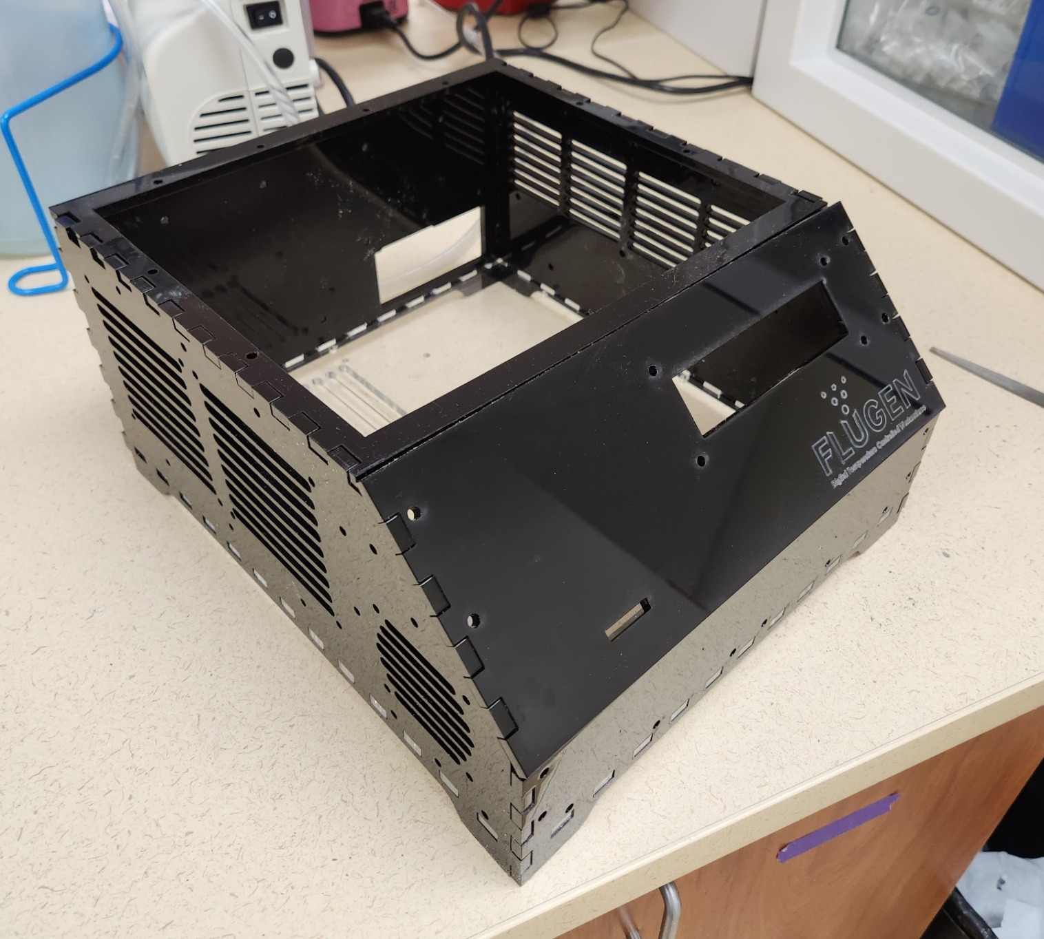
Mechanically, the DTCW was developed to be fully laser-cuttable and 3D printable, and also easy to service. I created a modified notched-box design which employs 3D printed brackets to connect the different sides. A major part of this design revolved around using heat set inserts, which I had never used in a design before. This ended up working remarkably well (plus they also look really cool)!
Manufacturing plus some design updates:
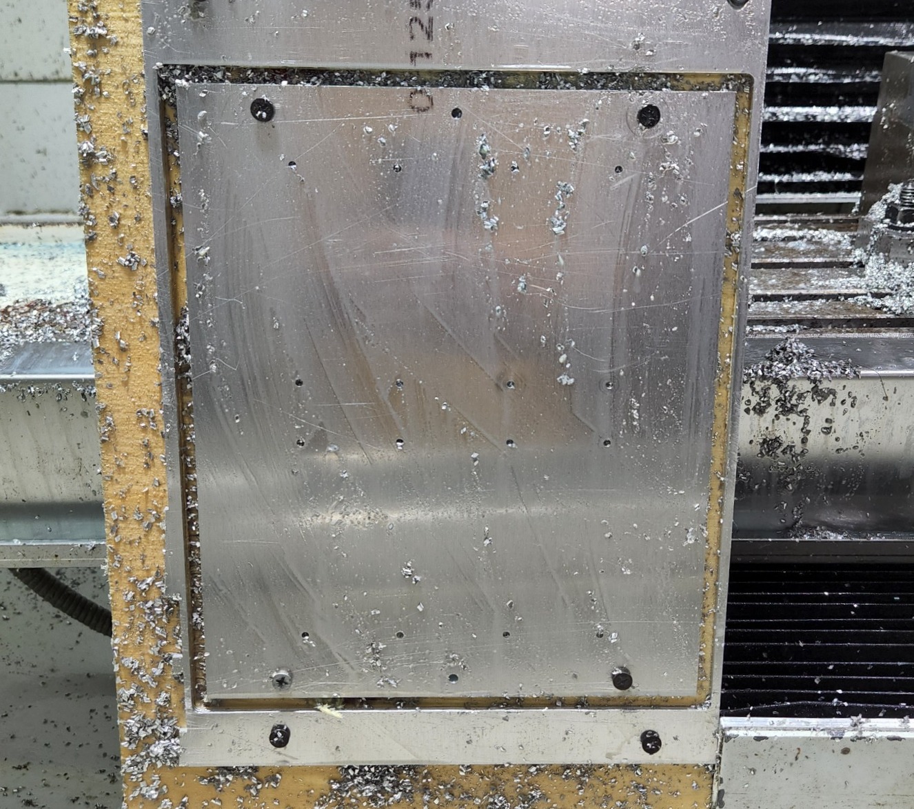
The first part to be manufactured was the aluminum cold plate, since I wanted to test my chiller design before spending a bunch of time in CAD to design the rest of the project. This was a fairly simple CNC milling operation. I made an incredibly basic wooden fixturing setup for the 1/8" aluminum plate, and screwed it down to the plate outside of the cut area. All the holes were drilled as the first operation, and then a perimeter cut pass was done to cut the part from the plate. This plate was a piece of scrap aluminum from a previous project I had left over. If I had to estimate the cost I would say $15-20 at the most.
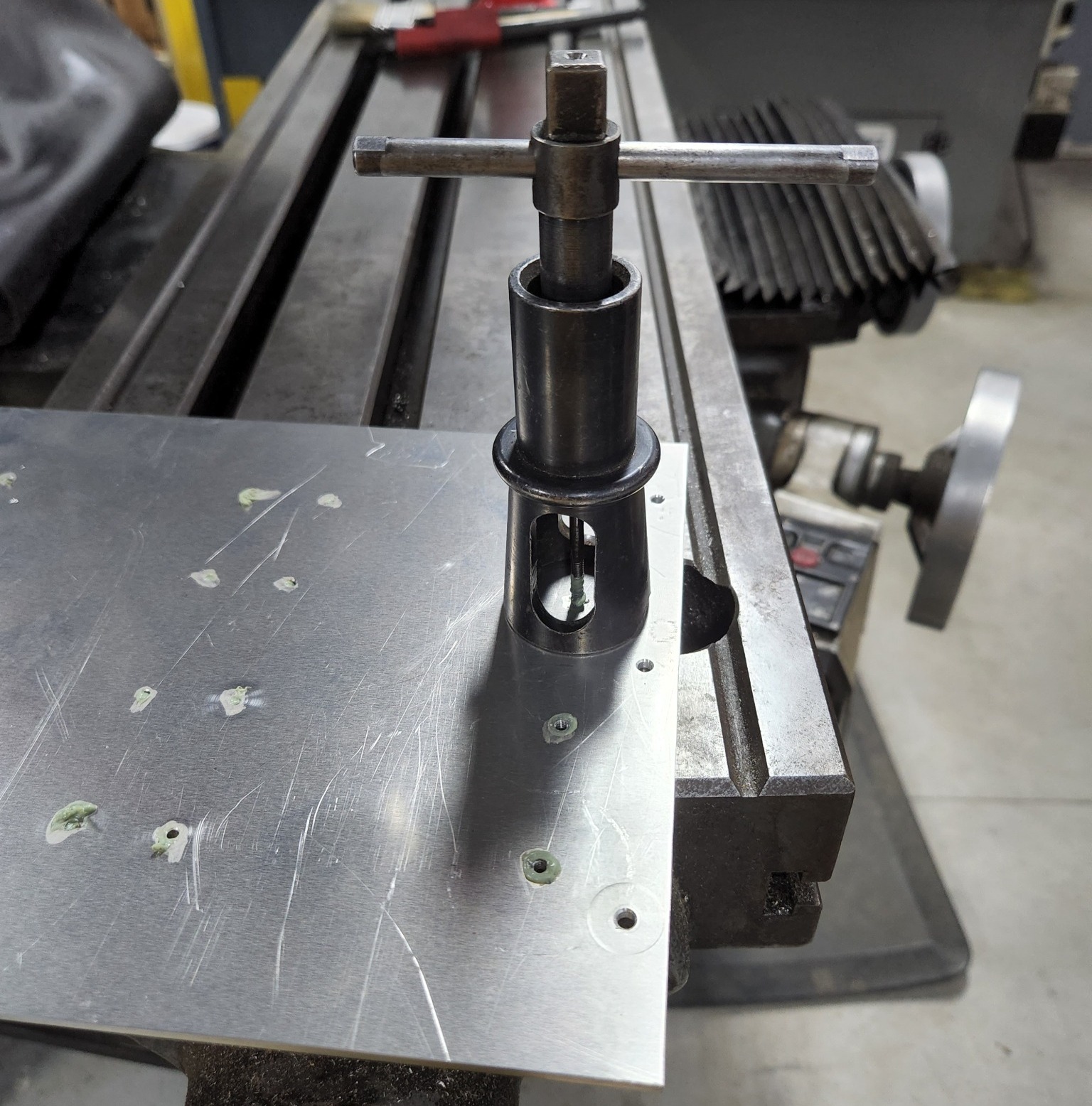
Next, the #6-32 holes for the heatsinks were tapped:
The next part of the cooler assembly was a laser cut polystyrene piece which acts as insulation for the two sides, and also acts as a spacer to keep the TEC modules from carrying too much clamping force. The polystyrene was $4 at the UW makerspace.
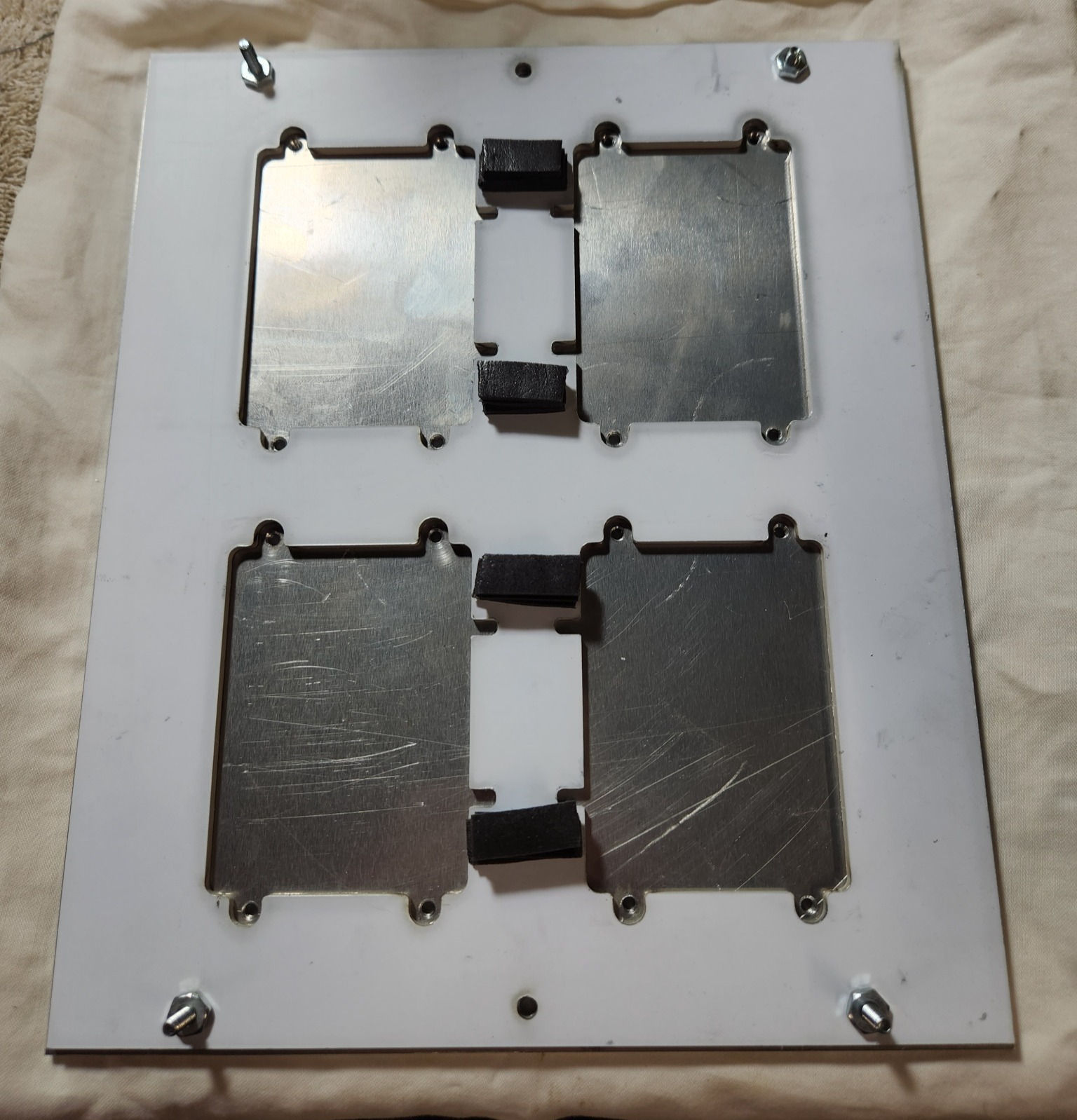
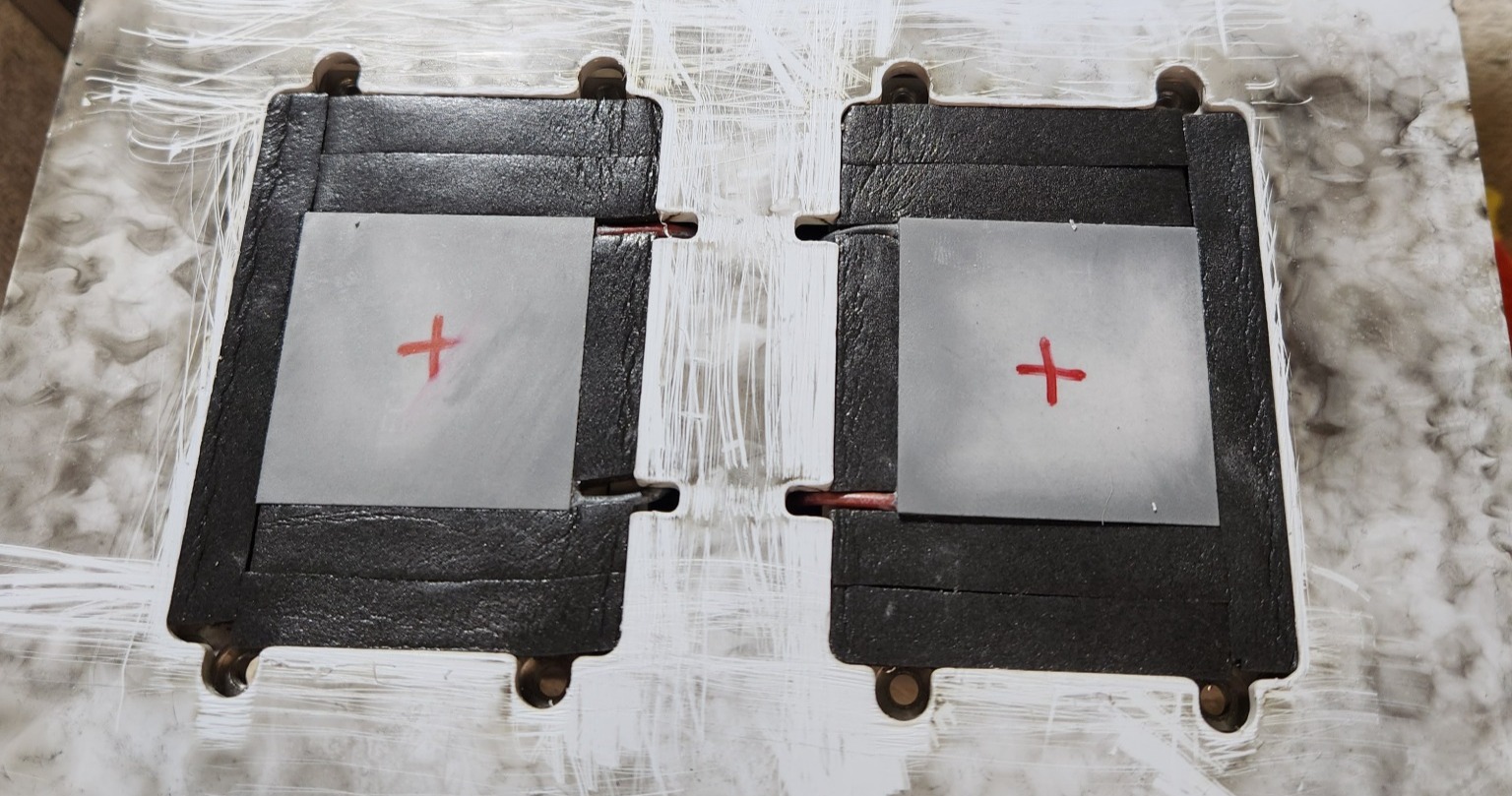
TEC modules were affixed to the bottoms of the heatsinks with a thin layer of thermal paste, and sticky-backed foam was applied around each TEC to insulate it more. All of the four TEC modules together cost approximately $30
Originally, I chose some very large Intel socket 604 heatsinks with heat pipes that I hoped would work well. The design was optimized for these and they fit perfectly with each other and would have had separate fans to blow air through them.
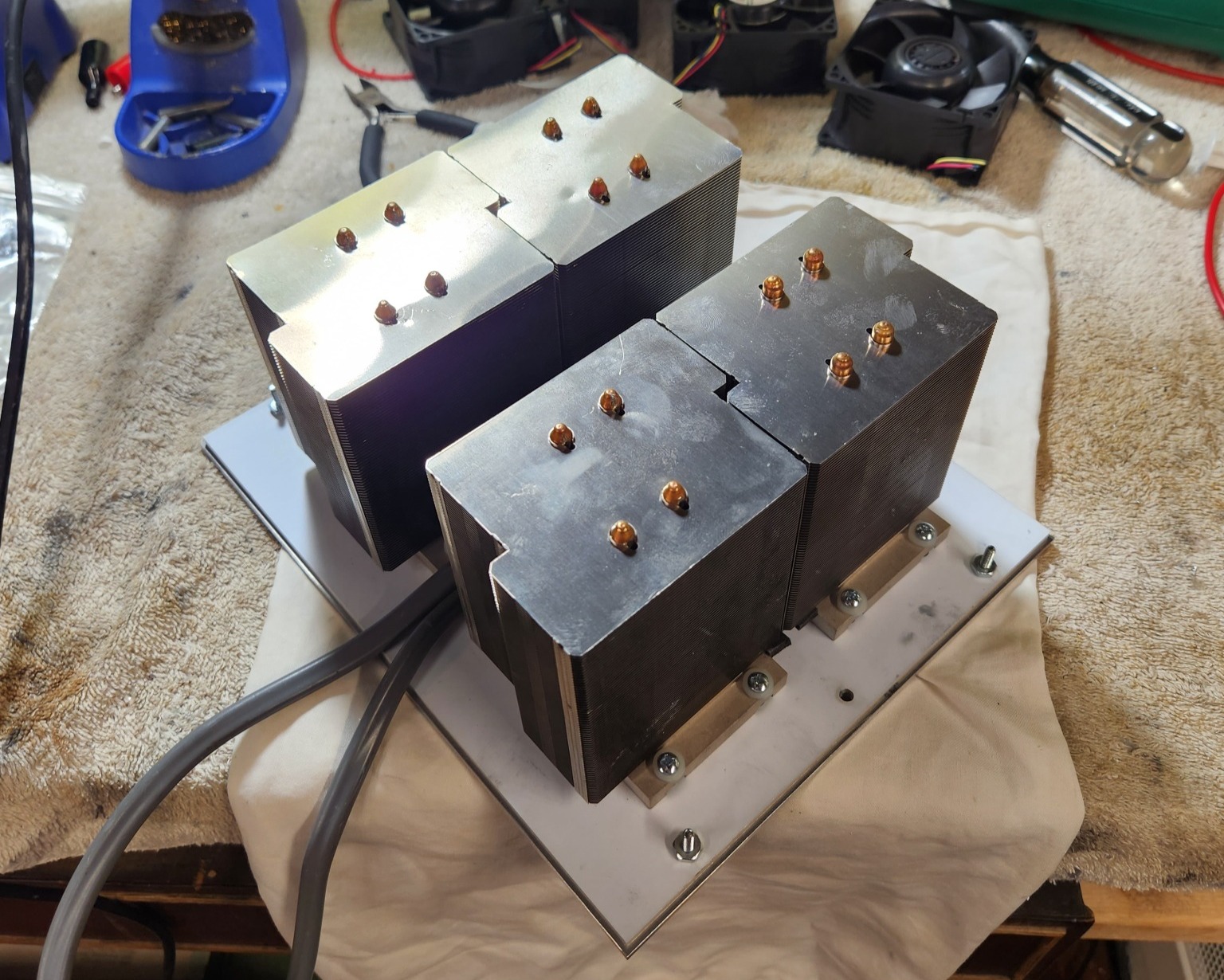
Unfortunately, as luck would have it, I had salvaged these from an old server, and the heat pipes in these heatsinks had dried out and no longer worked. A fact I only found out after running some load tests.
After a bit of searching, I was able to find a set of solid copper intel heatsinks for sale on eBay for about $35 to replace these ones. They had a completely different form factor but provided adequate cooling power for the TEC modules, and had built in fans.
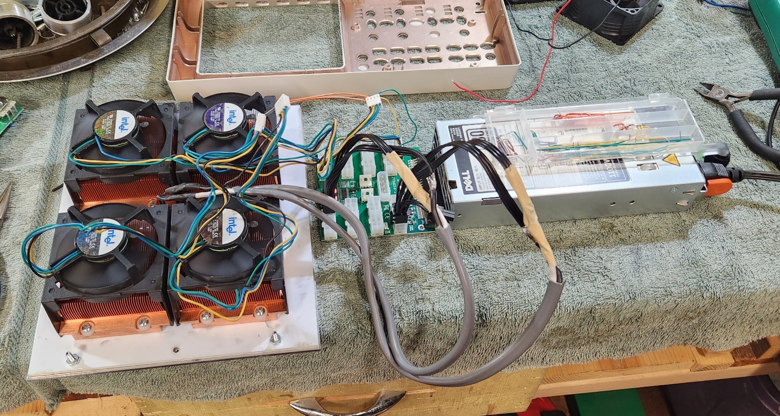
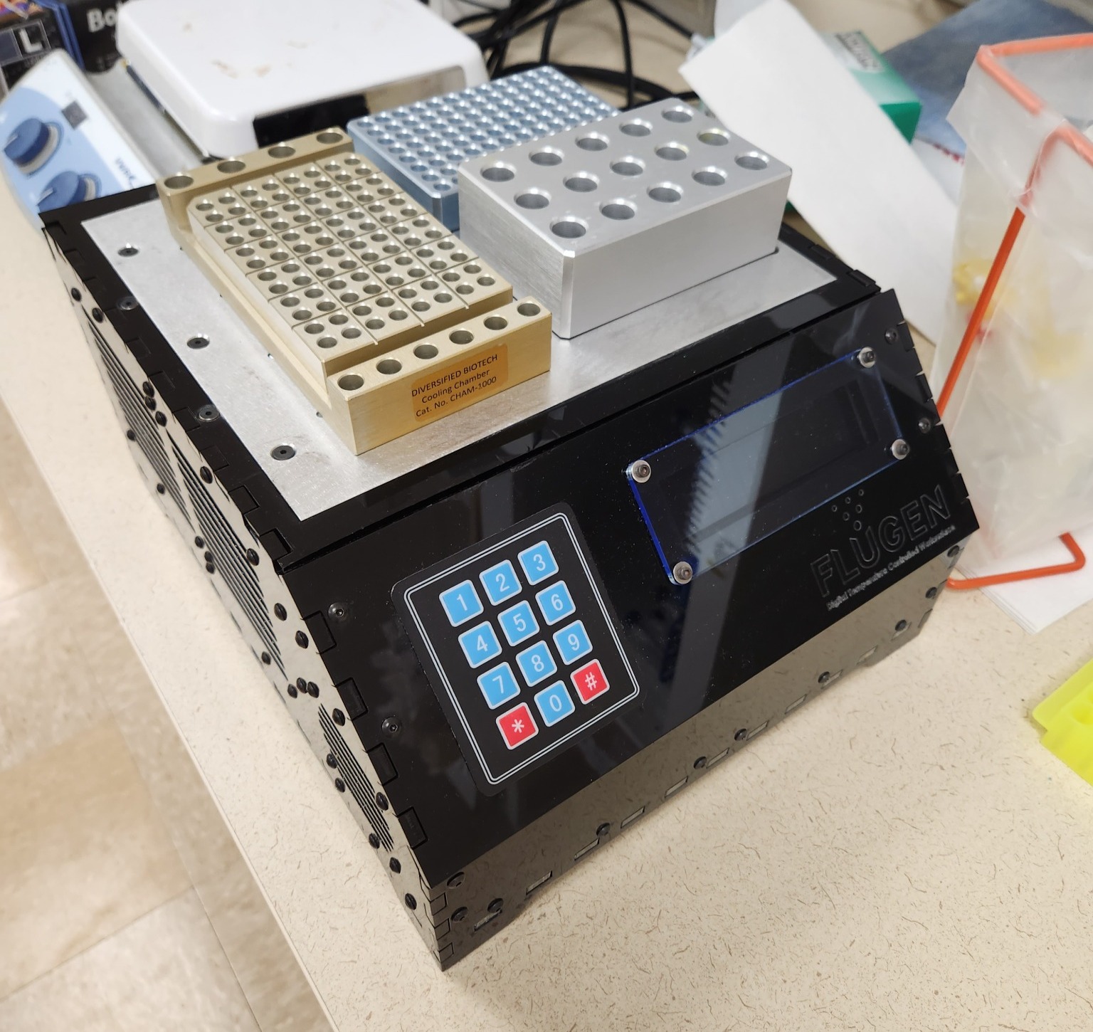
Using the final 1100W 12V Dell server PSU that I picked out for the project, plus a cheap adapter board originally meant for crypto mining, I was able to successfully run a stress test on the design to make sure it would work (~$30 on amazon + $15 for the adapter). After hooking everything up and making sure that it was operating as expected, as well as confirming that the hot side was not above 60C, I let it run for 2 hours straight. After coming back to it, the bench mat was incredibly cold, and it was still running great!
With the cooler working, I moved on to designing the rest of the DTCW for FDM 3D printing and laser cutting. I first started with a notched box design that had enough room for all the components and the angled front panel for the LCD and keypad, and then worked my way around the enclosure in CAD using assembly relations to position components and create correctly sized parts and holes for mounting them. I always strive to make my 3D designs highly modifiable if necessary, and this workflow lends itself nicely to this.
One of the smallest yet most satisfying details I added to the design was the ability to use the Dell power supply that I bought as it was intended, with a quick release mechanism and corresponding connector that it gets inserted into. A short GIF video shows this working below:
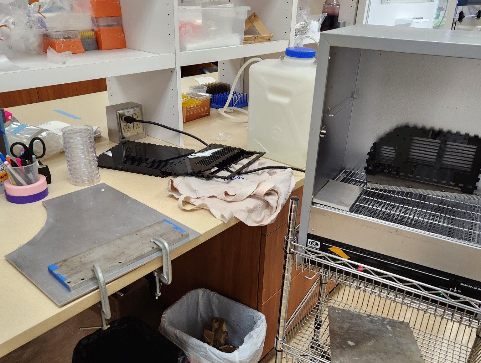
During manufacturing I ran into some issues with the acrylic enclosure pieces, specifically the ones with fan vents. The high number of cuts in such a small area led to the acrylic warping fairly strongly, enough to make the enclosure impossible to assemble. My solution to this was to heat the parts to Acrylic's softening temperature, and then use a metal plate with some clamps on one of FluGen's lab benchtops to flatten them out while they cooled down. This worked remarkably well, and they fit together well after.
In the future, if I was to make another DTCW, I would likely change these out for separate fan covers that are 3D printed or cut out of thinner acrylic, avoiding a buildup of heat in the acrylic enclosure panels during cutting.
After an unrelated bad hand injury that occurred when a glass shattered while washing dishes at home, I couldn't work at the lab for about two weeks. I took this downtime from lab work to really get started on knocking out the menu system code. Originally I was planning to just use one Arduino nano to power the whole system. However, between the 7 GPIO required for the keypad plus another 6 for the LCD, and the drop in performance that would come from running the PID loop and sensor reading on the same microcontroller, I opted to go for a split architecture. As mentioned before, one Arduino nano handles all the user inputs and the menu system on the LCD for the user to interact with. Through a RS-232 serial connection to the temperature controlling microcontroller (TCU), it requests information such as the current temperature, and sends the TCU setpoint values, settings, and diagnostic commands. Settings are saved permanently on the TCU in the EEPROM so they can be loaded at each boot. The total cost of the control systems came to less than $60 with the LCD, keypad, two Arduino nanos, the H-bridges and all of the Adafruit perfboard that I ended up building the permanent boards on.
Final thoughts
Overall the DTCW project was a huge success! It cost less than $260 in materials, it's been at FluGen now for about 4 months, and has a nice home on my supervisor's bench. It gets used nearly every day to help chill down samples while working on the bench, and he said it works far better than the little reusable ice packs he used to use. I also was able to incorporate so much knowledge I've gained as an engineer, and I learned an incredible amount about writing UIs for embedded devices. This project was incredibly fun overall, and is likely the most technically involved project I've ever taken on. Though there were issues while making it (warping acrylic, bad heatsinks, broken thermistors, code bugs, etc...) it didn't go through many revisions to be a super stable and practical tool, and both my supervisor and I are happy with the final version that lives at FluGen now.
Post a comment