Open-Frame 800W IPM Electric Motor Design Process
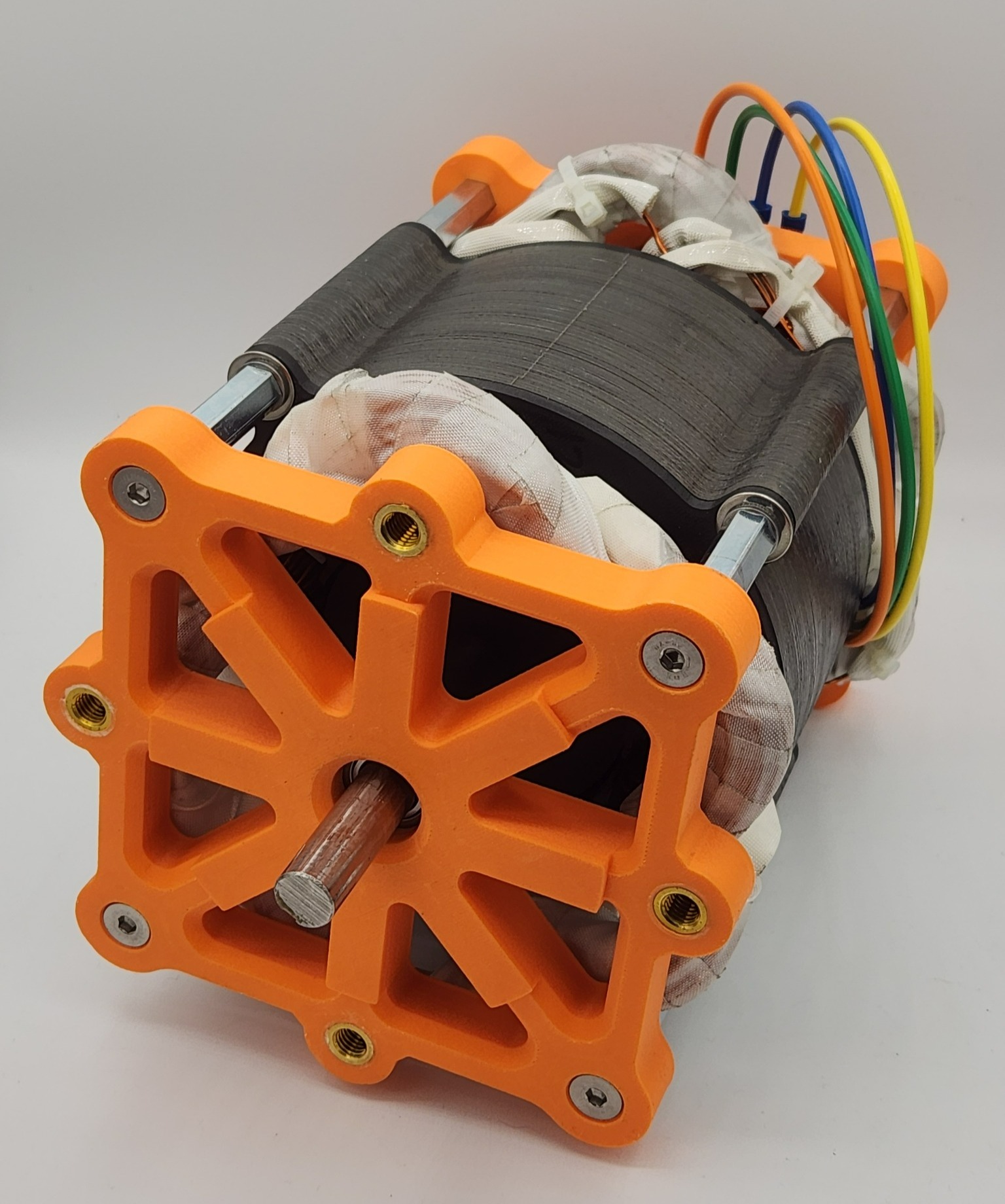
For some context, this project completed as the final deliverable for a year long capstone class for my BSME degree.
So you want to design a motor?
Although motors are an incredibly everyday item, consuming around 50% of the power on the electric grid every day, their design is somewhat of a mystery to most people, including myself prior to this project. The biggest questions I had were, where do you start? And what choices make the biggest impact on performance from a design perspective?
Perhaps the most important thing to decide on before planning the design of a motor is the type of motor that is required for the application. In our case, this motor was designed to be used in a instructional laboratory environment which focuses on the methods used to drive permanent magnet synchronous motors (PMSMs) as they are one of the most common types of motor. That left induction or reluctance motors out of the question, simplifying the decision considerably.
The exact list of requirements provided by our client is shown below:
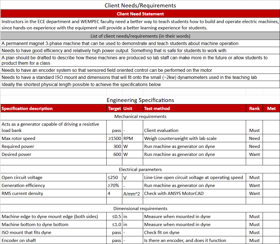
Translating these requirements into a physical prototype is easier said than done, but each individual requirement helps to mold a specific part of the design. E.g. max voltage limits the number of turns that can be used in each winding slot, RMS current density helps decide what AWG wire to use, and the dimensional requirements influence what methods are available to optimize performance since we are space constrained.
First decisions
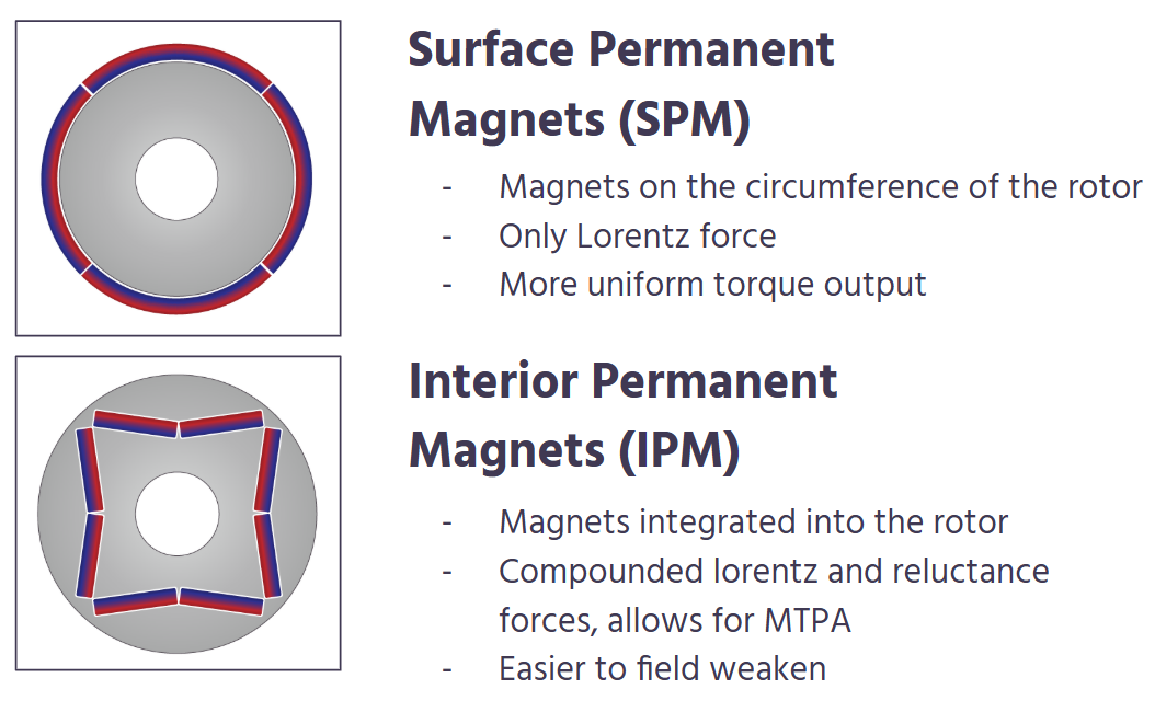
One of the most major decisions when designing a radial flux PMSM is the choice between SPM and IPM topologies. Both have pros and cons, especially when it comes to manufacturing. SPM requires physically curved magnets which need to be carefully bonded to the outside of a cylinder of magnetic steel. Especially at higher speeds it can become very challenging to prevent the magnets from tearing themselves off the rotor. Curved neodymium magnets also tend to be more expensive due to the strange geometry. The primary advantage of SPM motors is that their only torque producing mechanism is lorentz force, making them ideal for precision motion applications such as servos. Conversely, IPM machines are commonly seen in applications such as EVs where it is easier to manufacture high-speed rotors since the magnets are physically buried inside the rotor steel. The other major advantage over SPMs for electric vehicles is the ability to field weaken more easily since the airgap inductance is much higher (in an SPM, the magnet's thickness appears as part of the airgap, making the inductance very low). This is critical for high-speed highway operation. IPM machines can also take advantage of a control scheme called maximum torque per amp (MTPA), which determines when shifting some current onto the d-axis will produce extra torque from the dissimilar reluctance pathes through the rotor.
At the time of this project, I was an undergraduate student assistant (now a grad student) at WEMPEC, and was allowed access to their extensive software library and manufacturing capabilities for producing the machine design and manufacturing parts.
Post a comment