Tormach ZA6 pen plotter module
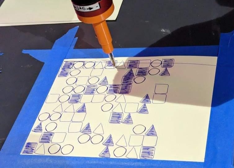
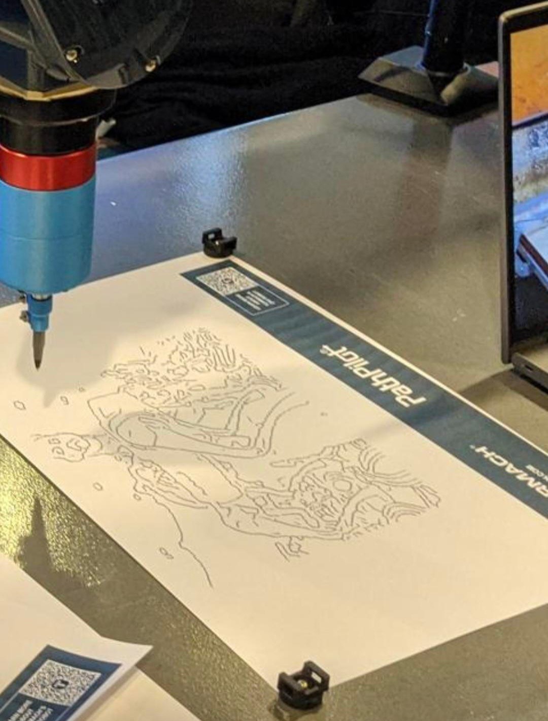
This project was created as the answer to a question that a good friend of mine, Sadiq, who works with a Tormach ZA6 arm asked: "How can we make a better pen mount for this thing?". He was working on generative code that drew shapes on paper with a pen holder that Tormach designed as a demo end-effector for the arm, but it lacked something essential: the ability to draw well. This was due to the spring-loaded pen carriage only being held concentric to the robot's wrist axis by a loosely fit 3D print; meaning that any time the robot moved while the pen was under pressure, the tip would lag behind the assumed position, causing drawings to come out looking incredibly sloppy.
If you're interested in making your own copy of this design, I have pushed SOLIDWORKS design files, mechanical drawings, and STLs for 3D printing this model to my GitHub page.
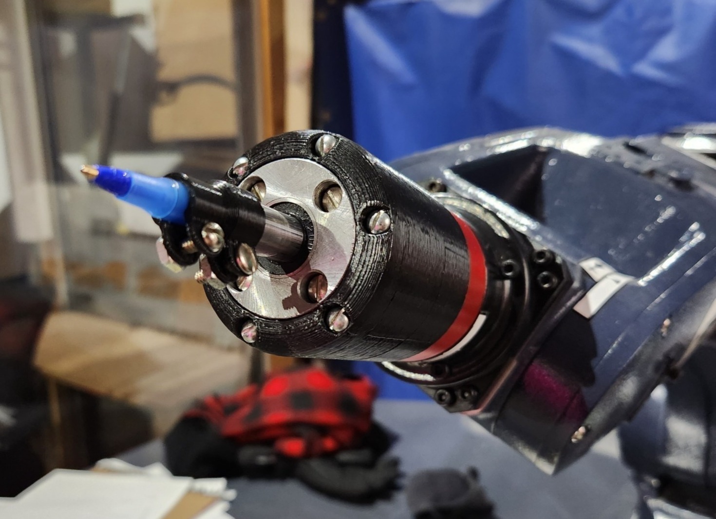
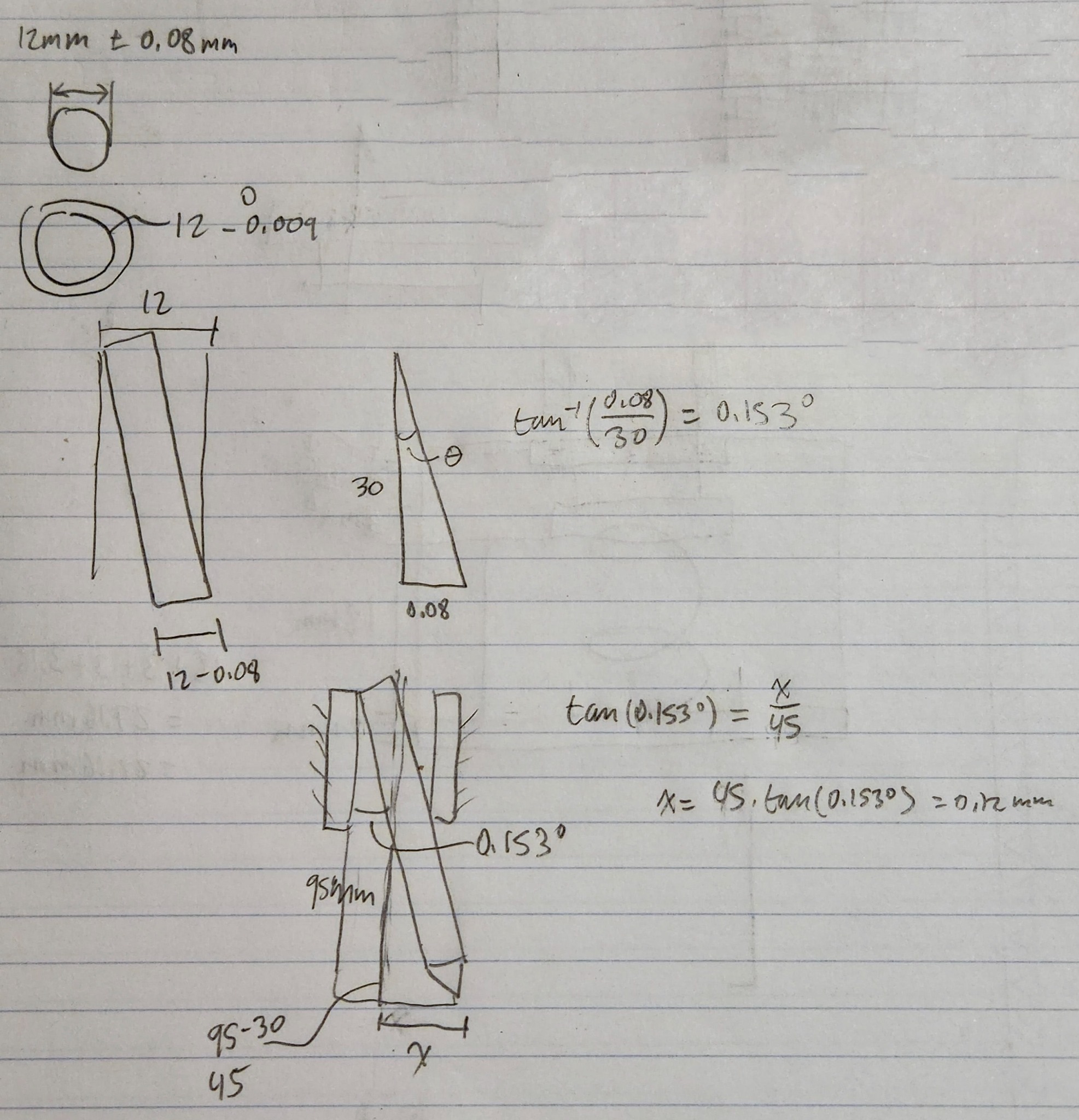
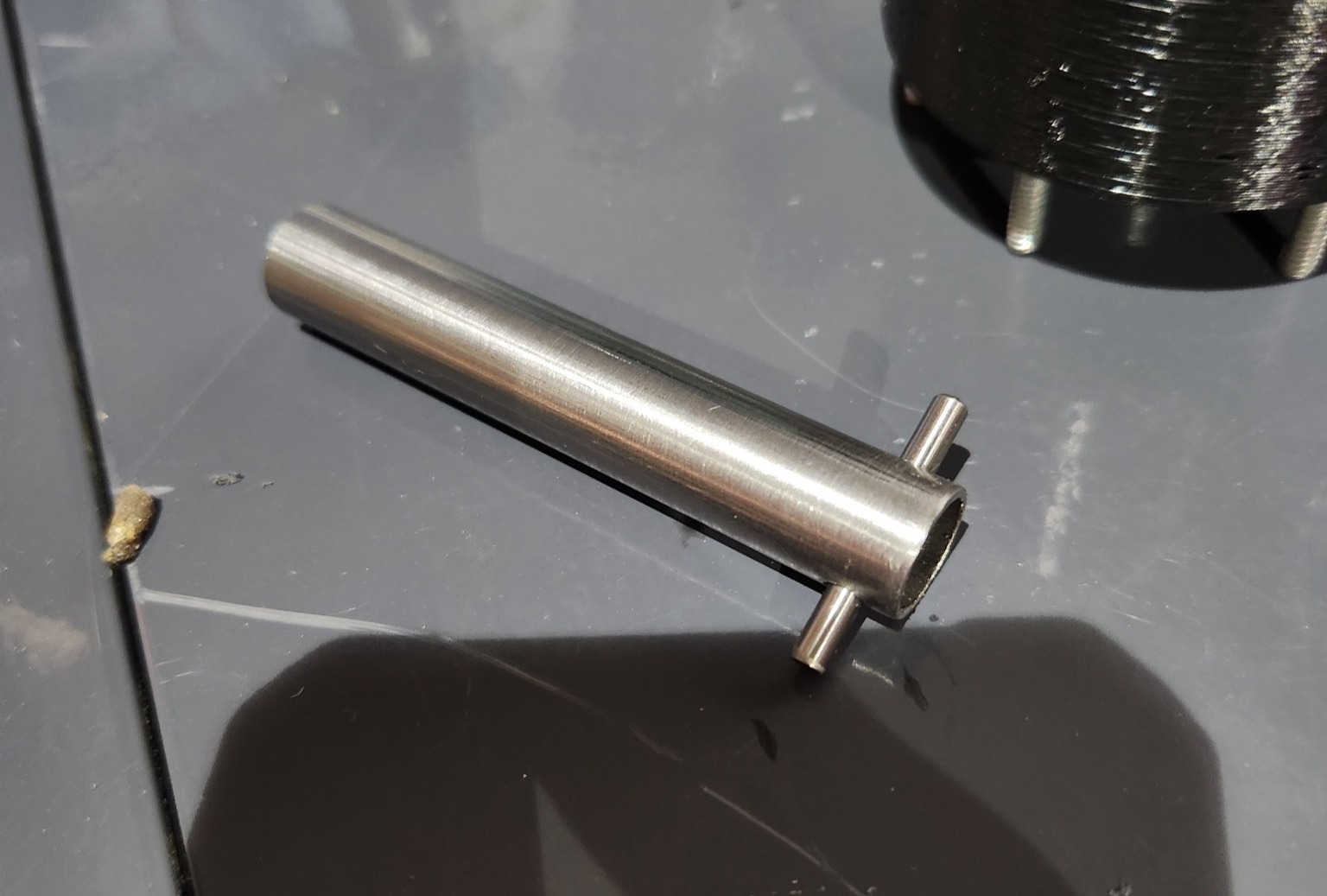
The design constraint requiring the pen tip to stay concentric with the center of the robot's wrist axis, plus needing tight tolerance wasn't an easy issue to solve. I ended up settling on a system which uses a section of steel tubing running through a 12mm linear bearing to keep the pen carriage from deflecting sideways while drawing. Using trigonometry and some tolerance information from McMaster Carr, I determined that the maximum deflection of the end of the pen would be 0.12mm with the new setup, assuming no other deflections or bending stresses.
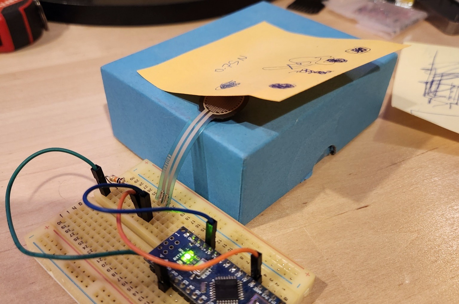
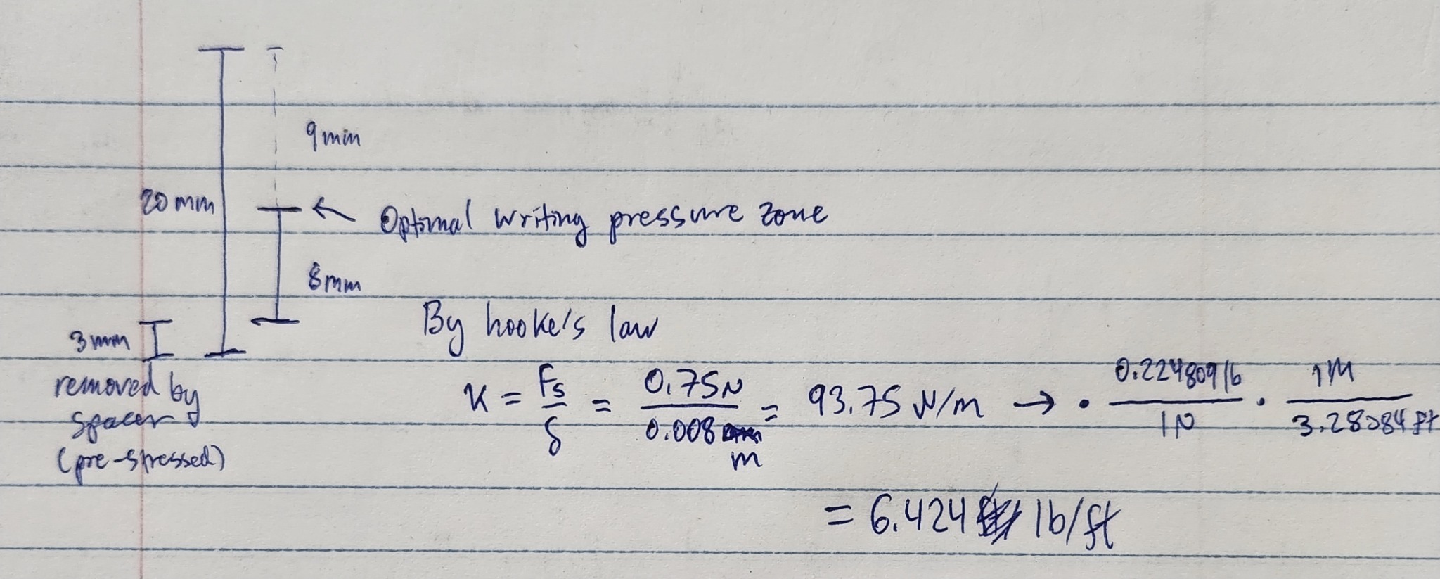
Next, we wanted to fix another issue present in the last design: excessive pen pressure. Compounded with minimal pen travel length, this was causing the paper to tear frequently. The old design had only 7mm of total travel length, but we planned to shoot for around 17mm of travel, giving a larger range of pen pressure and greater reliability when drawing on a non-flat surface. Using a physical test setup with a resistive pressure sensor and some sheets of paper, we determined that a sufficient writing pressure was ~0.75N. Taking this information into account, I used Hooke's law and desired deformation length to place the force "sweet spot" slightly below the midpoint of the pen travel.
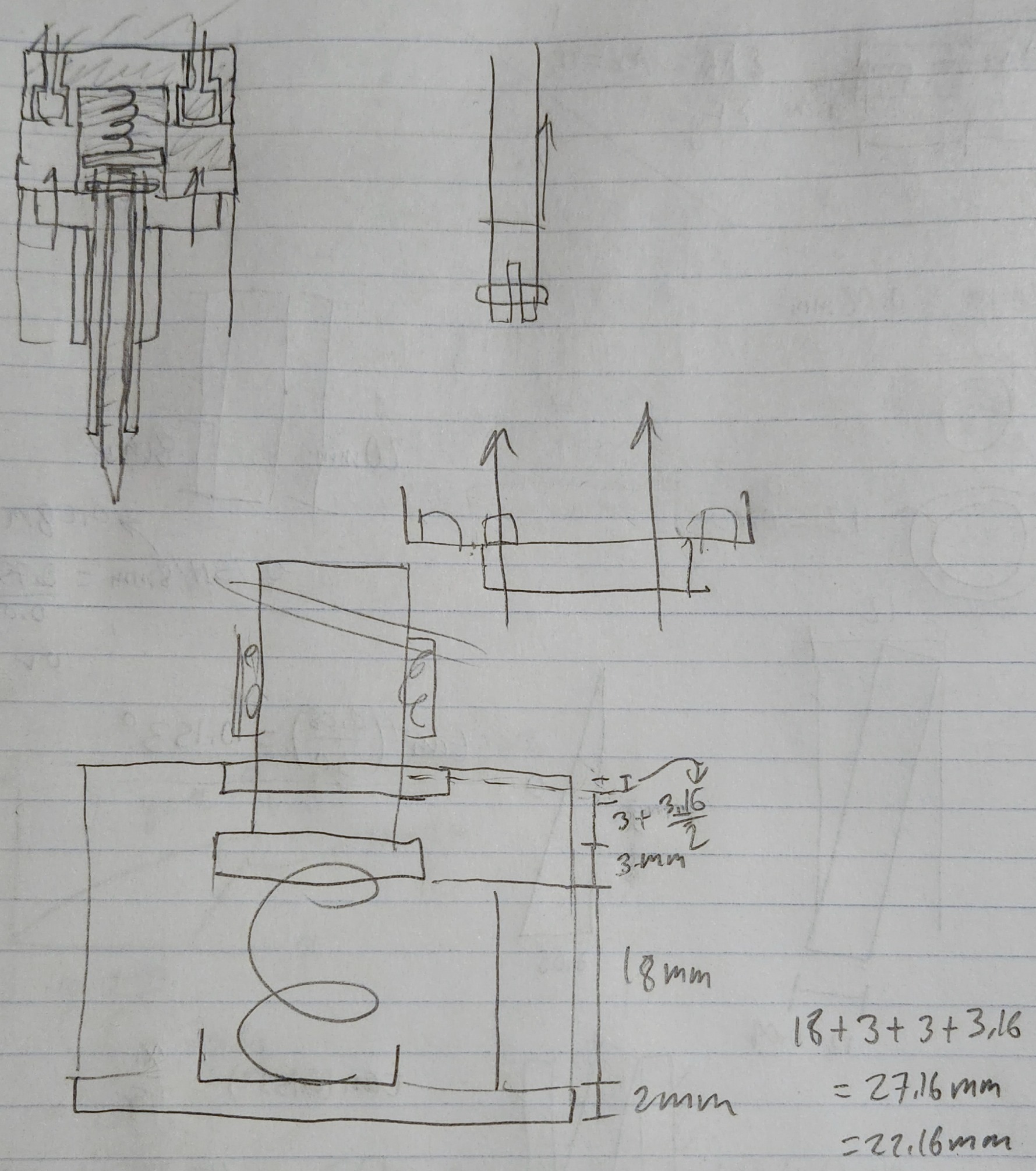
Turning the design ideas and calculations into a functional 3D model was the next step. First, I conceptualized the design on paper by sketching the rough layout of how parts would have to fit together and where fasteners would fit into the model.
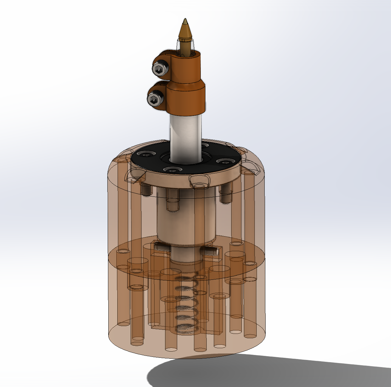
With this worked out, I turned to SOLIDWORKS to make a fully flushed-out 3D model with all the correct dimensions.
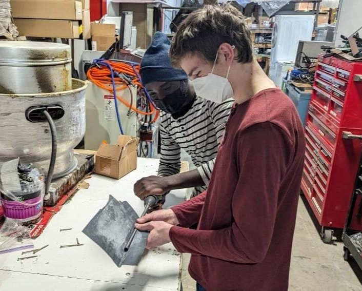
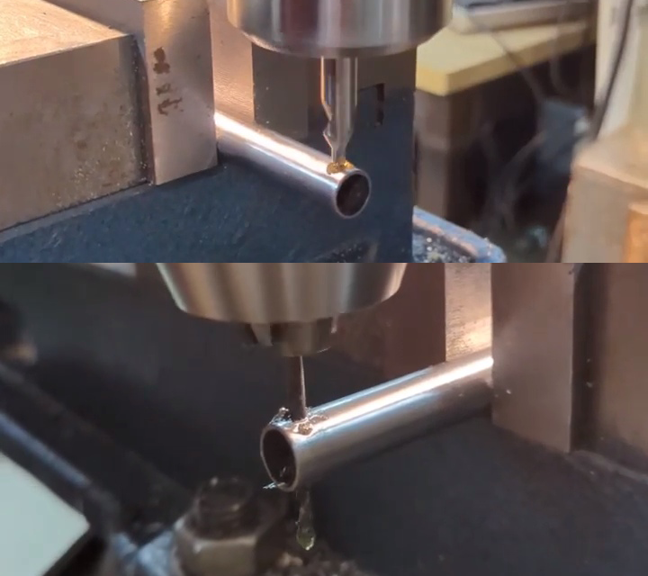
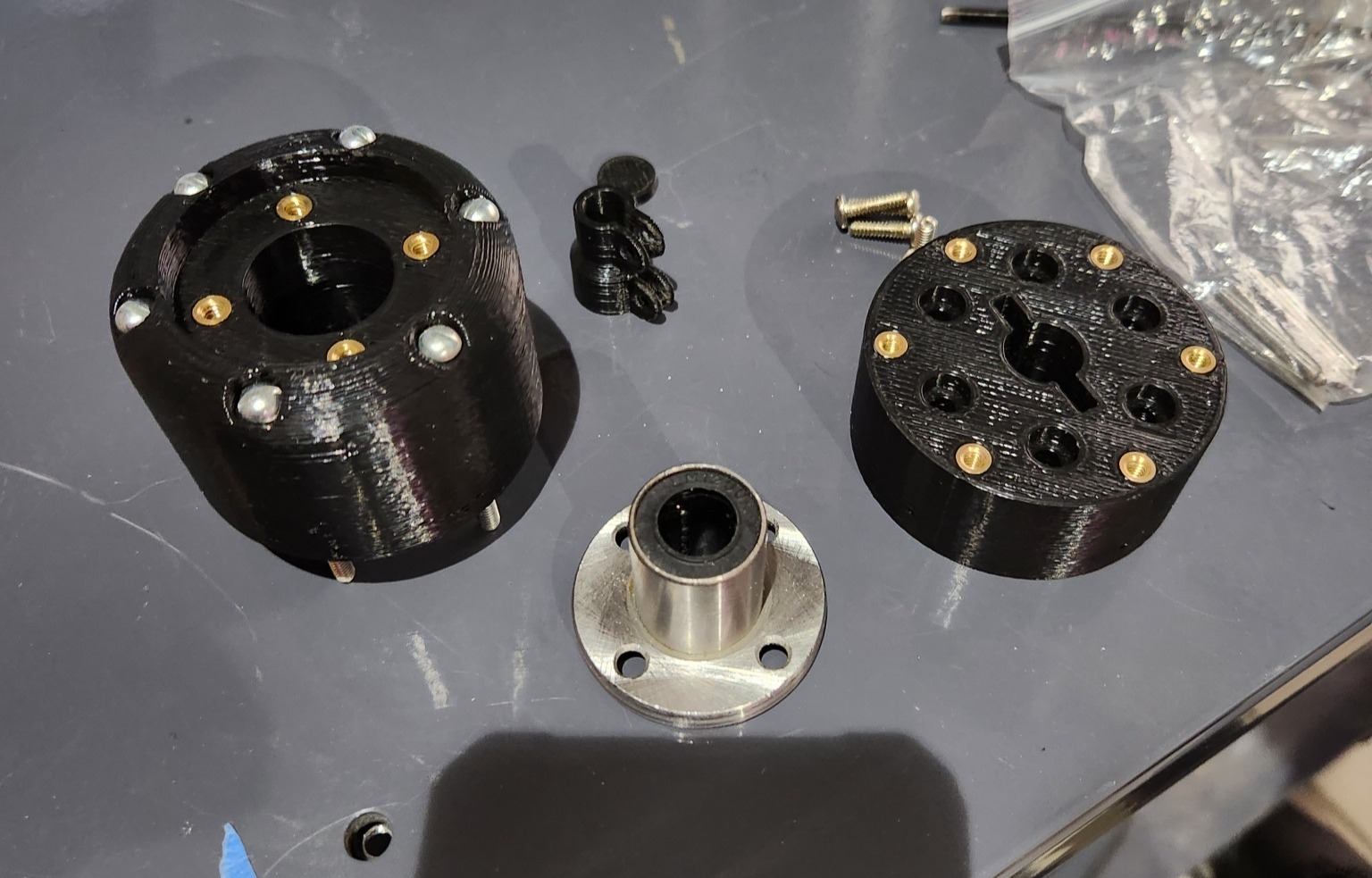
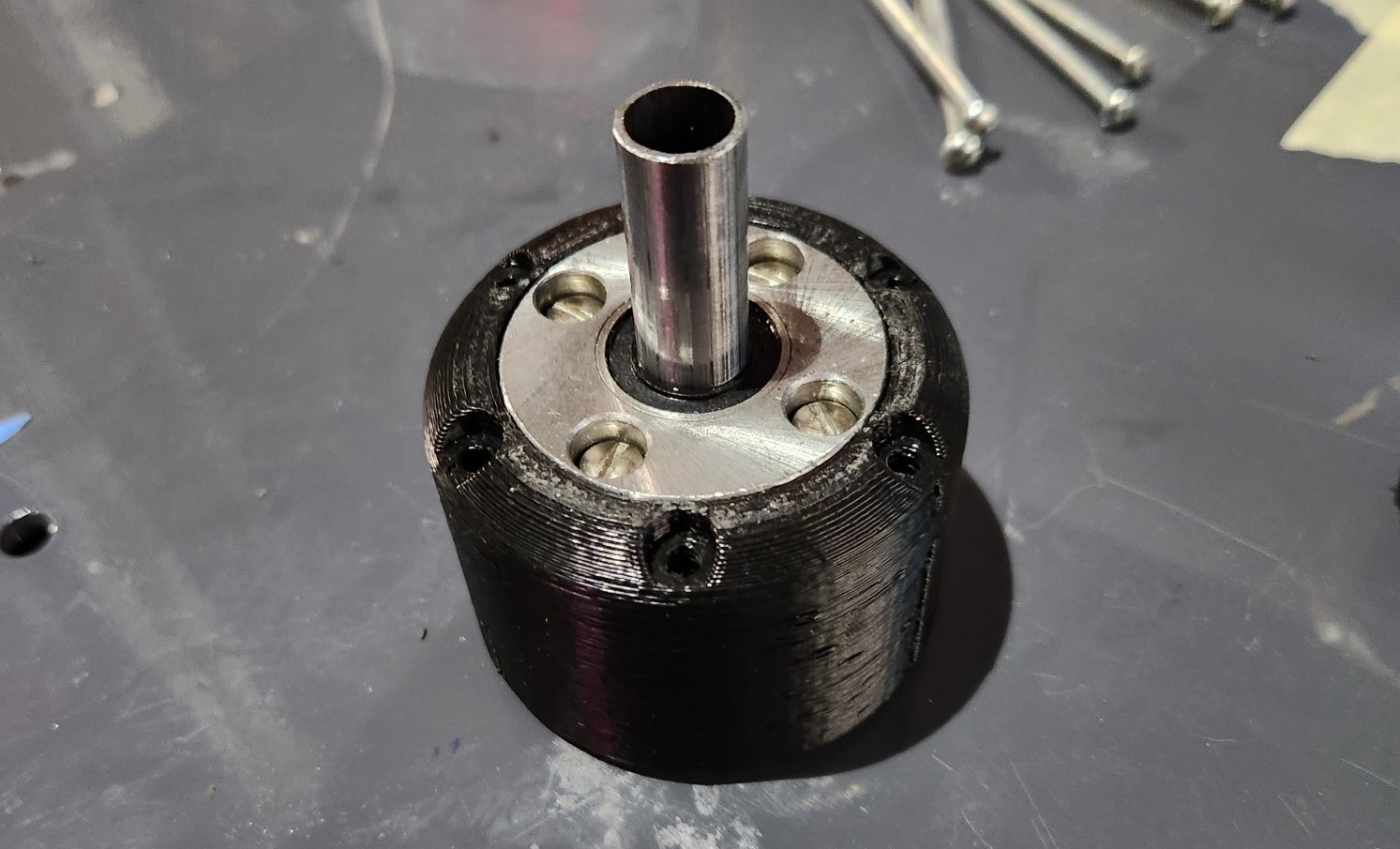
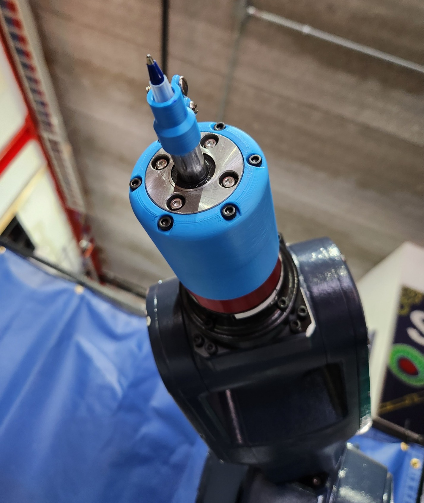
And finally, after 3D printing the parts, we were ready to assemble it in real life. Unfortunately, the tubing had a tolerance on its diameter which could trend positive from 12mm, meaning that it wouldn't move smoothly through the 12mm bearing and our particular section of tube was fairly far into that region. To fix this, we had to use high-grit sandpaper and carefully shrink the tube's diameter until the bearing moved smoothly. In a future revision, it's likely that we will replace this with case-hardened steel shaft that has a hole bored down the center for the pen, as the low-carbon steel tubing we used is far less resilient to wear from the bearing and may fail prematurely.
Immediately after drawing with the new pen module, the differences in results were astounding. Lines were perfectly straight, and the robot could draw with precision, bringing Sadiq's dreams to reality. I will let the video below drawing the same test pattern as earlier speak for me:
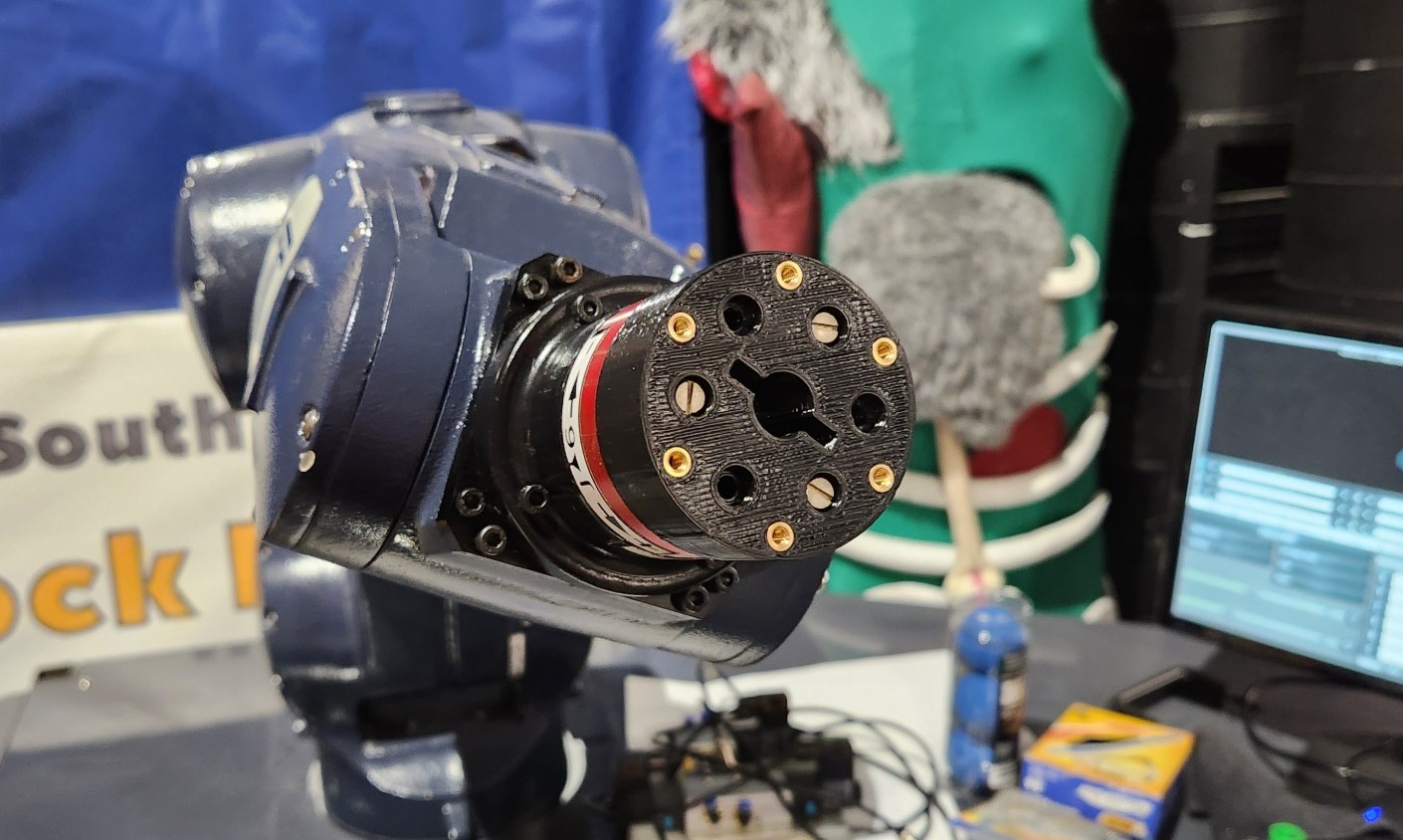
Finally, after some more extensive testing, we determined that the travel length was still a bit on the short side, and after some quick modifications and a new spring, we had a brand new model with slightly more travel (and a much cooler looking color):
Since completing it at the beginning of the year, during Sadiq's internship for Tormach, it's been featured at both ROSCon 2023 to do live drawings of participants at the show, and also featured in an interview with Sadiq at the company headquarters.
Post a comment