Lithium ion 18650 cell discharger and charger
This project was made out of necessity for the massive amount of 18650 cells I was storing while testing them for other projects like my electric trike battery. My battery testers (Opus BT-C3100s and Liitokala Lii 500s) both leave cells at 4.2v after running a capacity test and there is no option to reduce the storage voltage (e.g. adding a final partial discharge cycle). There is considerable evidence (Table 2) to show that storing lithium ion cells at room temperature at 100% SOC will greatly decrease their capacity over even a couple months of storage. Decreasing the SOC to around 40% (~3.7v) is a common method of reducing this damage during storage, and it is used worldwide by many battery manufacturers. Unfortunately tools to do this are not commonplace or cheap, so I had to make my own.
I came up with a rather simple design that would allow for both charging and discharging by using relays to switch between off-the-shelf charging modules and appropriately sized power resistors.
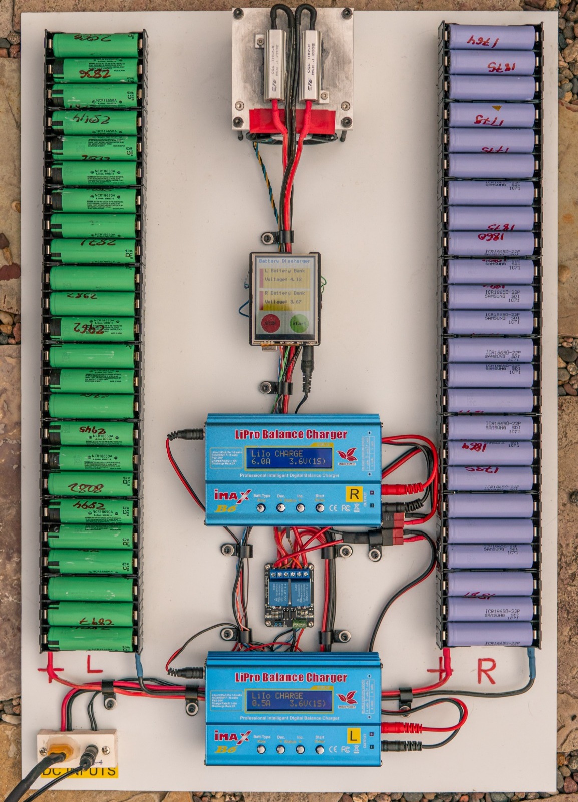
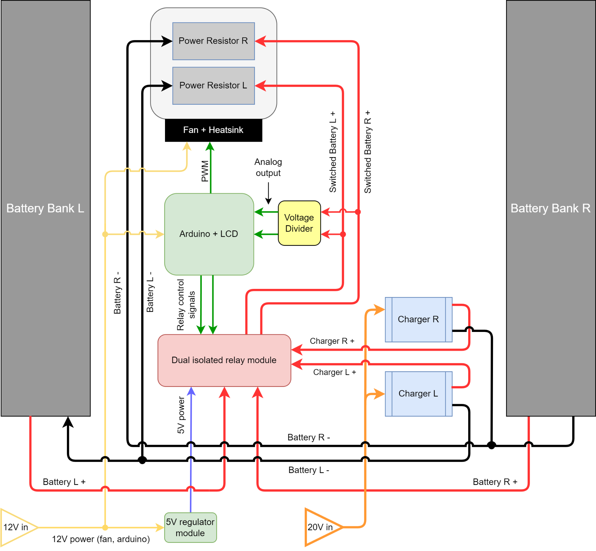
This diagram is the basic principle of how the discharger was designed. Two separate banks of 24 18650 cells are independently controlled and switched by the Arduino user interface. Either bank can be charged or discharged depending on the state set by the software, and in the discharging state, the positive side of the battery banks are switched to the 0.5 ohm power resistors at the very top which dissipate heat into the heatsink/fan combo (an old intel stock cooler).
From some basic calculations, I chose 0.5 ohms since at the working voltage of the batteries it will draw 6-8.4A (3-4.2V) depending on their state of charge, which translates to a very modest 0.25-0.35A per cell if all 24 are loaded, which is the use case I designed it for.
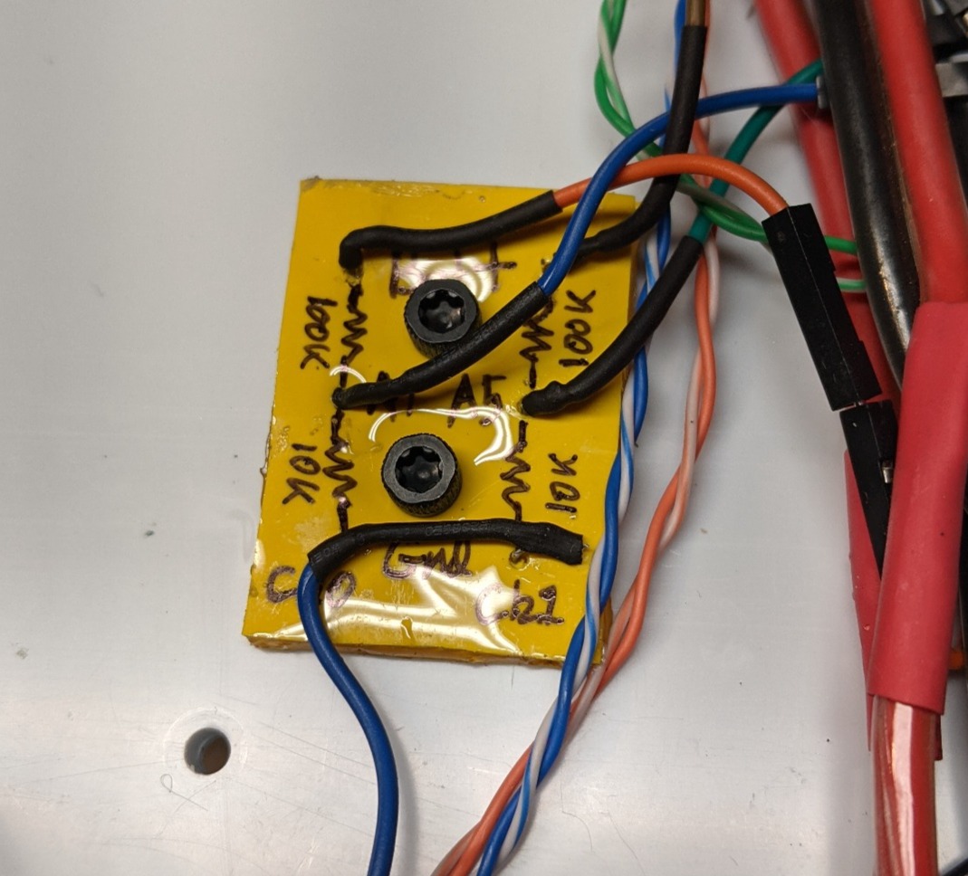
To keep voltage stable when no cells were inserted and to remove slight charge from the battery chargers when idle, I used a voltage divider with a very modest gain of 0.91 (100K/(10K+100K)) to achieve this. I ended up having to add some 0.1uf decoupling capacitors to remove extra noise later as well.
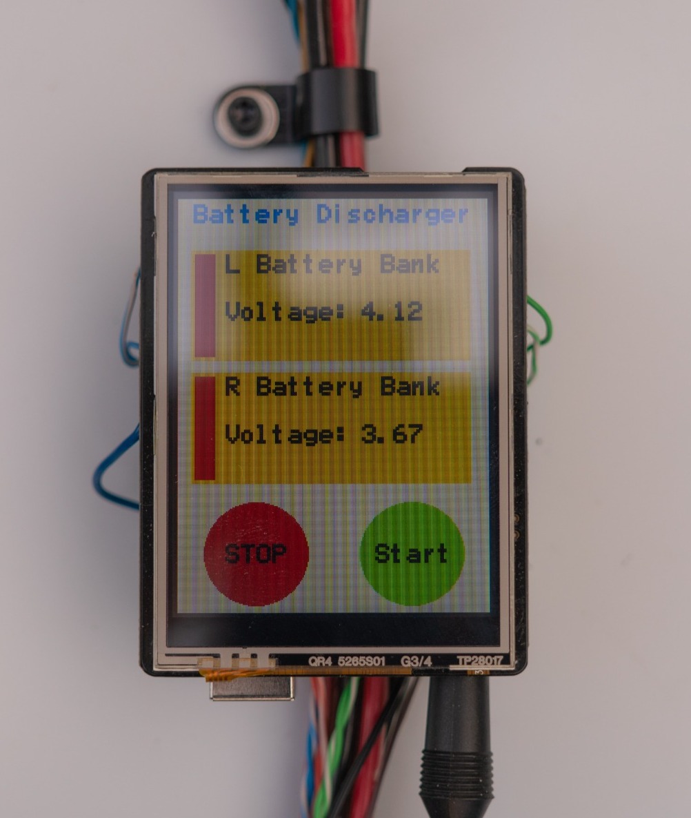
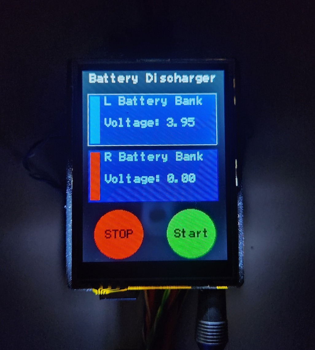
The last part was creating the user interface for controlling the discharger. This was actually my first time ever doing serious C++ programming, and I had never really used an Arduino on my own before, so I took it as an opportunity to push myself and learn from it! The original firmware looked exactly like the photo above, and the user was able to select from either channel and start or stop it using the giant buttons below. It would automatically cut off discharging at 3.7V and ramp the fan according to how many channels were running.
There were a couple bugs that occasionally caused it to fail to show that the discharge cycle had ended, and some odd behavior close to the 3.7V setpoint. I redid the UI to be nicer looking with custom colors and fixed all the bugs for the system. This was the final revision:
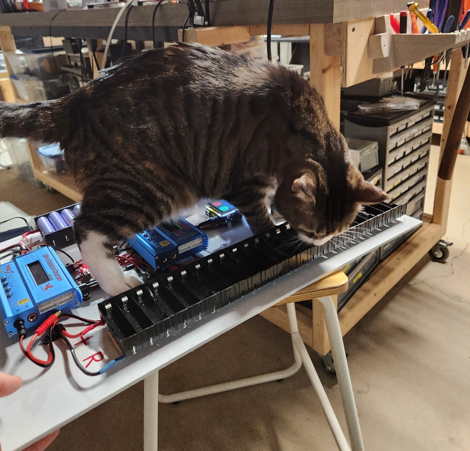
The discharger had one last test to pass before I started using it regularly, and this was the cat inspection. She came to check all the wiring and the software and it was given a passing grade, so it was finally ready for use!
The control code for the Arduino is publicly available on my Github page if you are interested in how it was written!
Post a comment